NAVTEX RECEIVER
NX-700A/B
Pub. No. OME-56490 HIMA NX-700A/B
00015280402 00015280402
OME56490C00 OME56490C00
FIRST EDITION : MAY. C : JUN. 15,
IMPORTANT NOTICE
SAFETY INSTRUCTIONS
Safety information for the Operator
ELECTRICAL SHOCK HAZARD
a FURUNO agent or dealer about replacement
Safety information for the Installer
Attach securely protective
FORWORD
Features
SYSTEM CONFIGURATIONS
TABLE OF CONTENTS
3. MAINTENANCE & TROUBLESHOOTING
4. INSTALLATION
AP-1
SPECIFICATIONS
INTERCONNECTION DIAGRAM
SP-1
viii
EQUIPMENT LISTS
Standard Supply
Name
Type
Optional Supply
Name
Code No
SYSTEM CONFIGURATIONS
1.1How NAVTEX Works
1.PRINCIPLE OF NAVTEX SYSTEM
1.2NAVTEX System Operation
1.3Message Format
1.4NAVTEX Station Map
1. PRINCIPLE OF NAVTEX SYSTEM
1.5NAVTEX Station List
Continued on next page
Country
Station
area
Country
Country
2.2Turning the Unit On/Off
2.OPERATION
2.1Operating Controls
Display unit, front view
2.3Adjusting LCD Dimmer
All message display 518 kHz
SAR Search and Rescue message
2.4Confirming the New Message
Other messages
Message list
2.5Sample Messages
Detailed message
Receive Mode Manual
2.6Choosing the Receive Mode
NAVTEX
Manual
490kHz
2.8Editing the Settings for Station and Message
2.7Choosing the Local Frequency
Local channel options
Station
Rcv Station & Msg
Auto
Message
Switching the frequency to display
2.9Switching the Frequency to Display
2.10Alarm Messages
When receiving SAR Search and Rescue message
List options
2.11Processing Messages
Choosing messages to display
Urgent message
All Messages
2.12Printing Messages
2-10
Protecting message from deleting
Canceling printing
2-11
User Select
Printing each message
INS Input Speed
2.13Editing the NAVTEX Station List
2-12
Service menu
NavArea
2-13
Station
Oostende
2-14
NavArea
Edit
2.14Icons
2-15
Icon
Message
2.15Messages List
2-16
Meaning
NAVTEX menu
2.16Other Functions
2-17
System menu
Display menu
2-18
Setting
Item
Setting
2-19
Service menu
Item
This page is intentionally left be blank
2-20
2. OPERATION
Maintenance program
3.MAINTENANCE & TROUBLESHOOTING
3.1Maintenance
Item
Fuse
3.2Replacement of Fuse, Battery and Thermal Paper
Battery
Use the proper fuse
Thermal paper NX-700Aonly
3.3Troubleshooting
Memory test
3.4Diagnostics
Key Test
Key test
3.5Restoring all Default Settings
Rx test
4.1Display Unit
4.INSTALLATION
Tabletop, overhead mounting
For NX-700A
Flush mounting
For NX-700B
General mounting considerations
4.2Receiver Unit
Mounting Method
4.3Antenna Unit
Mounting considerations
4.5Wiring
4.4Printer NX-700Bonly
Receiver unit
Receiver unit, inside view
How to use J402 and 403 connector
Antenna cable
For RG-10/UY, RG-214cable
Extending antenna cable length
OP04-2 To Receiver unit FMA-1connector
Grounding
Warn Msg Alm
4.6Setting of Printer
4-10
NX-700A
Priority
4.7Digital Interfacing
4-11
Input data sentence description
4-12
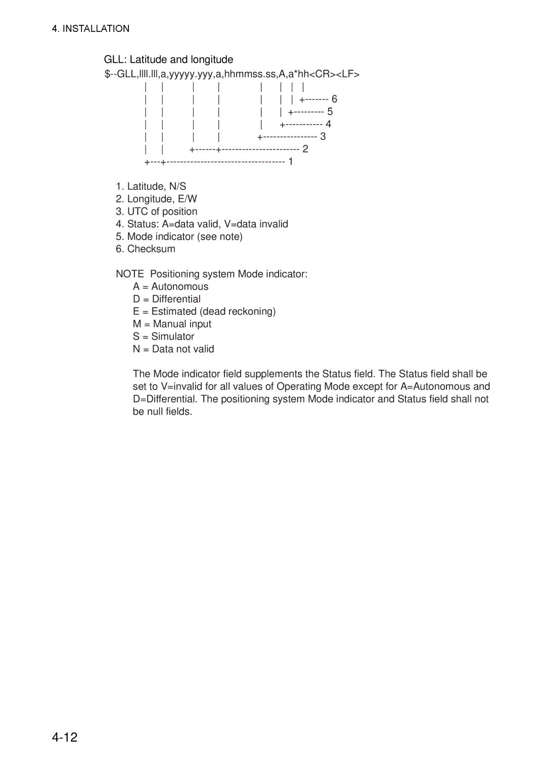
GLL: Latitude and longitude
4-13
RMC: Recommend Minimum Specific GNSS Data
4-14
ZDA: Time and date
NRQ: Request NAVTEX messages
4-15
NMK: Set NAVTEX mask
$--ACK,xxx*hh<CR><LF>
4-16
1.Local alarm numberidentifier 2.Checksum
ACK: Acknowledge
4-17
$--VHW,x.x,T,x.x,M,x.x,N,x.x,K*hh<CR><LF>
4-18
$--VBW,x.x,x.x,A,x.x,x.x,A,x.x,A,x.x,A*hh<CR><LF>
Output data description
4-19
NRX: New NAVTEX received message
ALR: Set alarms
4-20
Serial Interface
MENU TREE
AP-1
NAVTEX RECEIVER
FURUNO SPECIFICATIONS OF NAVTEX RECEIVER
NX-700A/B
DISPLAY UNIT
ANTENNA UNIT
FURUNO
POWER SUPPLY
INTERFACE
NX-700A/NX-700A-HK/NX-700A-R
PACKING
LIST
ACCESSORIES
PACKING
NX-700B/NX-700B-HK/NX-700B-R
INSTALLATION MATERIALS
LIST
PACKING
NX-7001-AN*/BN*/-R
INSTALLATION MATERIALS
LIST
PACKING
NX-7001-AA-*/BA
INSTALLATION MATERIALS
LIST
PACKING
NX-7H-0-10/-10-HK,NX-7H-0-20/-20-HK
INSTALLATION MATERIALS
LIST
工事材料表
004-514-530
INSTALLATION MATERIALS
工事材料表
08AW-X-9402
004-514-540
INSTALLATION MATERIALS
工事材料表
08AW-X-9403
工事材料表
INSTALLATION MATERIALS
08AW-X-9407
工事材料表
A-10
INSTALLATION MATERIALS
004-514-610
FURUNO ELECTRIC CO.,LTD
A-11
SPARE PARTS LIST FOR
U S E
Page
Page
Page
Page
Page
取付位置
D-ー66
Page
INDEX
IN-1
0560
FURUNO ELECTRIC CO., LTD
Declaration of conformity