Safety information for the Installer
![]() WARNING
WARNING
| Do not open the equipment | |
| unless totally familiar with | |
| electrical circuits and | |
| service manual. | |
ELECTRICAL | Only qualified personnel | |
should work inside the | ||
SHOCK | ||
HAZARD | equipment. |
Turn off the power at the mains switch- board before beginning the installation.
Fire, electrical shock or serious injury can result if the power is left on or is applied while the equipment is being installed.
![]() CAUTION
CAUTION
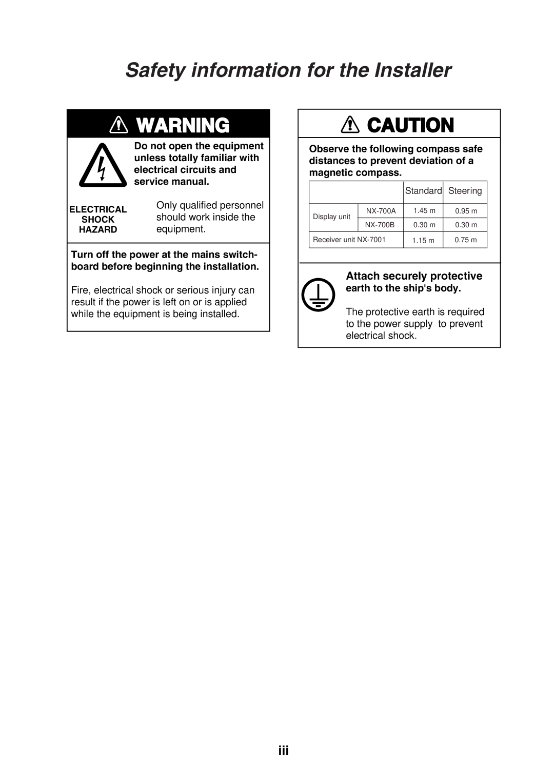
Observe the following compass safe distances to prevent deviation of a magnetic compass.
|
| Standard | Steering | |
|
|
|
| |
Display unit | 1.45 m | 0.95 m | ||
0.30 m | 0.30 m | |||
| ||||
Receiver unit | 1.15 m | 0.75 m | ||
|
|
|
| |
Attach securely protective
earth to the ship's body.
The protective earth is required to the power supply to prevent electrical shock.
iii