|
|
|
|
| CODE NO. |
|
|
|
| |
|
|
|
|
|
|
|
|
|
| 1/1 |
|
|
|
|
| TYPE |
|
| |||
|
|
|
|
|
|
|
|
|
| |
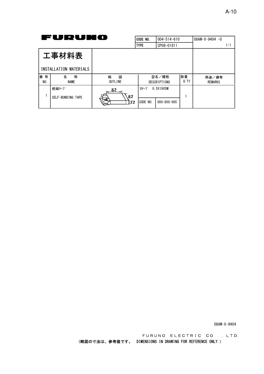
工事材料表 |
|
|
|
|
|
|
|
| ||
INSTALLATION MATERIALS |
|
|
|
|
|
|
|
| ||
|
|
|
|
|
|
|
|
|
|
|
番 号 | 名 | 称 | 略 | 図 |
|
| 型名/規格 | 数量 | 用途/備考 | |
NO. |
| NAME | OUTLINE |
| DESCRIPTIONS | Q'TY | REMARKS | |||
|
|
|
|
|
|
|
|
|
|
|
| 絶縁テープ |
|
|
|
| Uテープ | 0.5X19X5M |
|
| |
1 |
|
|
|
|
|
| 1 |
| ||
|
|
|
|
|
| CODE NO. |
|
| ||
|
|
|
|
|
|
|
|
|
|
|
FURUNO ELECTRIC CO .,LTD.
(略図の寸法は、参考値です。 DIMENSIONS IN DRAWING FOR REFERENCE ONLY.)
|
|
|
|
| CODE NO. |
|
|
|
| |
|
|
|
|
|
|
|
|
|
| 1/1 |
|
|
|
|
| TYPE |
|
| |||
|
|
|
|
|
|
|
|
|
| |
工事材料表 |
|
|
|
|
|
|
|
| ||
INSTALLATION MATERIALS |
|
|
|
|
|
|
|
| ||
|
|
|
|
|
|
|
|
|
|
|
番 号 | 名 | 称 | 略 | 図 |
|
| 型名/規格 | 数量 | 用途/備考 | |
NO. |
| NAME | OUTLINE |
| DESCRIPTIONS | Q'TY | REMARKS | |||
|
|
|
|
|
|
|
|
|
|
|
| 絶縁テープ |
|
|
|
| Uテープ | 0.5X19X5M |
|
| |
1 |
|
|
|
|
|
| 1 |
| ||
|
|
|
|
|
| CODE NO. |
|
| ||
|
|
|
|
|
|
|
|
|
|
|
FURUNO ELECTRIC CO .,LTD.
(略図の寸法は、参考値です。 DIMENSIONS IN DRAWING FOR REFERENCE ONLY.)