2. OPERATION
2.16Other Functions
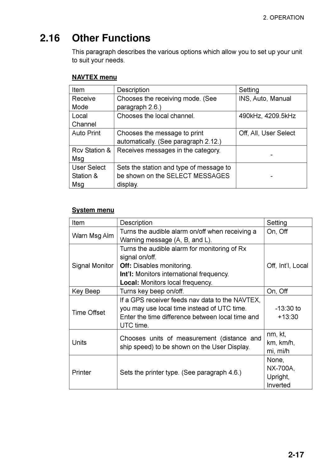
This paragraph describes the various options which allow you to set up your unit to suit your needs.
NAVTEX menu
Item | Description | Setting |
Receive | Chooses the receiving mode. (See | INS, Auto, Manual |
Mode | paragraph 2.6.) |
|
Local | Chooses the local channel. | 490kHz, 4209.5kHz |
Channel |
|
|
Auto Print | Chooses the message to print | Off, All, User Select |
| automatically. (See paragraph 2.12.) |
|
Rcv Station & | Receives messages in the category. | - |
Msg |
| |
|
| |
User Select | Sets the station and type of message to |
|
Station & | be shown on the SELECT MESSAGES | - |
Msg | display. |
|
System menu
Item | Description | Setting | |
Warn Msg Alm | Turns the audible alarm on/off when receiving a | On, Off | |
| Warning message (A, B, and L). |
| |
| Turns the audible alarm for monitoring of Rx |
| |
| signal on/off. |
| |
Signal Monitor | Off: Disables monitoring. | Off, Int’l, Local | |
| Int’l: Monitors international frequency. |
| |
| Local: Monitors local frequency. |
| |
Key Beep | Turns key beep on/off. | On, Off | |
| If a GPS receiver feeds nav data to the NAVTEX, |
| |
Time Offset | you may use local time instead of UTC time. | ||
Enter the time difference between local time and | +13:30 | ||
| |||
| UTC time. |
| |
Units | Chooses units of measurement (distance and | nm, kt, | |
km, km/h, | |||
| ship speed) to be shown on the User Display. | mi, mi/h | |
|
| ||
|
| None, | |
Printer | Sets the printer type. (See paragraph 4.6.) | ||
Upright, | |||
|
| ||
|
| Inverted |