INTRODUCTION
Congratulations, and thank you for your purchase of the RFX ABC904 Route 3 switcher. This unit was designed and manufactured to provide years of faithful service. Please review this manual carefully - so you have a proper understanding of the operation of your new ABC904.
The ABC904 is a versatile unit that works as a signal distribution device by taking a single stereo or mono signal input, and switching it to up to three stereo outputs. The unit can also take three separate stereo or mono signals in, and switch them to a single stereo or mono output.
WARRANTY
For information on the Rolls One Year Limited Warranty, and to register this product, visit our website at www.rolls.com
DESCRIPTION
Common Jacks: Two 1/4”
A,B,C Jacks: Three 1/4”
A,B,C Switches: Mechanical latching switches - connect and disconnect the A,B,C jacks to the Common jack(s).
BATTERY: Houses the 9V battery for powering the indicator LEDs.
CONNECTION
First, it must be stressed that the ABC904 should | Figure 1 |
either be operated in Stereo, or Mono mode |
|
-NOT both. Using this device with mono cabling and stereo equipment could damage your stereo equipment.
Since the ABC904 is a passive device, connect- ing a mono
will be grounded. This means the stereo signal will be lost.
Therefore, you must first determine whether you operating this unit in Stereo or Mono. Refer to Figure 1 for the differences in Stereo and Mono 1/4” plugs.
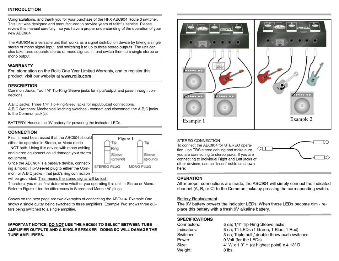
Shown on the next page are two examples of connecting the ABC904. Example One shows a single guitar being switched to three amplifiers. Example Two shows three gui- tars being switched to a single amplifier.
IMPORTANT NOTICE: DO NOT USE THE ABC904 TO SELECT BETWEEN TUBE AMPLIFIER OUTPUTS AND A SINGLE SPEAKER - DOING SO WILL DAMAGE THE TUBE AMPLIFIERS.
Example 1 | Example 2 |
| |
|
|
STEREO CONNECTION
To connect the ABC904 for STEREO opera-
tion, use TRS stereo cabling and make sure ![]()
![]()
![]() you are connecting to stereo jacks. If you are connecting to individual Right and Left jacks of
you are connecting to stereo jacks. If you are connecting to individual Right and Left jacks of
other devices, use an “Insert” cable as shown here:
OPERATION
After proper connections are made, the ABC904 will simply connect the indicated channel (A, B, or C) to the Common jacks by pressing the corresponding switch.
Battery Replacement
The 9V battery powers the indicator LEDs. When these LEDs become dim - re- place this battery with a fresh 9V alkaline battery.
SPECIFICATIONS |
|
Connectors: | 5 ea; 1/4” |
Indicators: | 3 ea; T1 LEDs (1 Green, 1 Blue, 1 Red) |
Switches: | 3 ea; Triple pull / double throw push switches |
Power: | 9 Volt (for the LEDs) |
Size: | 4” W x 1.9” H (at highest point) x 4.13” D |
Weight: | 3 lbs. |