SCHEMATIC |
5 |
DESCRIPTION
FRONT PANEL
|
|
|
|
|
|
|
|
|
|
|
|
|
|
|
|
|
|
|
|
|
|
|
|
|
|
|
|
|
|
|
|
|
|
| FOUR |
|
|
| ZONE |
|
|
|
|
|
| ZONE |
|
|
|
|
|
| ZONE |
|
|
|
|
|
|
|
| ZONE | |||||||||
|
| SELECT |
|
|
|
| SELECT |
|
|
|
| SELECT |
|
|
|
|
|
|
| ||||||||||||||||
| 1 | 2 | 3 | 4 | 5 | 6 | 7 | 8 |
|
| 1 | 2 | 3 | 4 | 5 | 6 | 7 | 8 |
|
| 1 | 2 | 3 | 4 | 5 | 6 | 7 | 8 |
|
|
|
|
| pwr | MIXER |
LEVEL | 1 2 3 4 1 2 3 4 | LEVEL | LEVEL | 1 2 3 4 1 2 3 4 | LEVEL | LEVEL | 1 2 3 4 1 2 3 4 | LEVEL | LEVEL | LEVEL | LEVEL | LEVEL | RM64 | ||||||||||||||||||||||
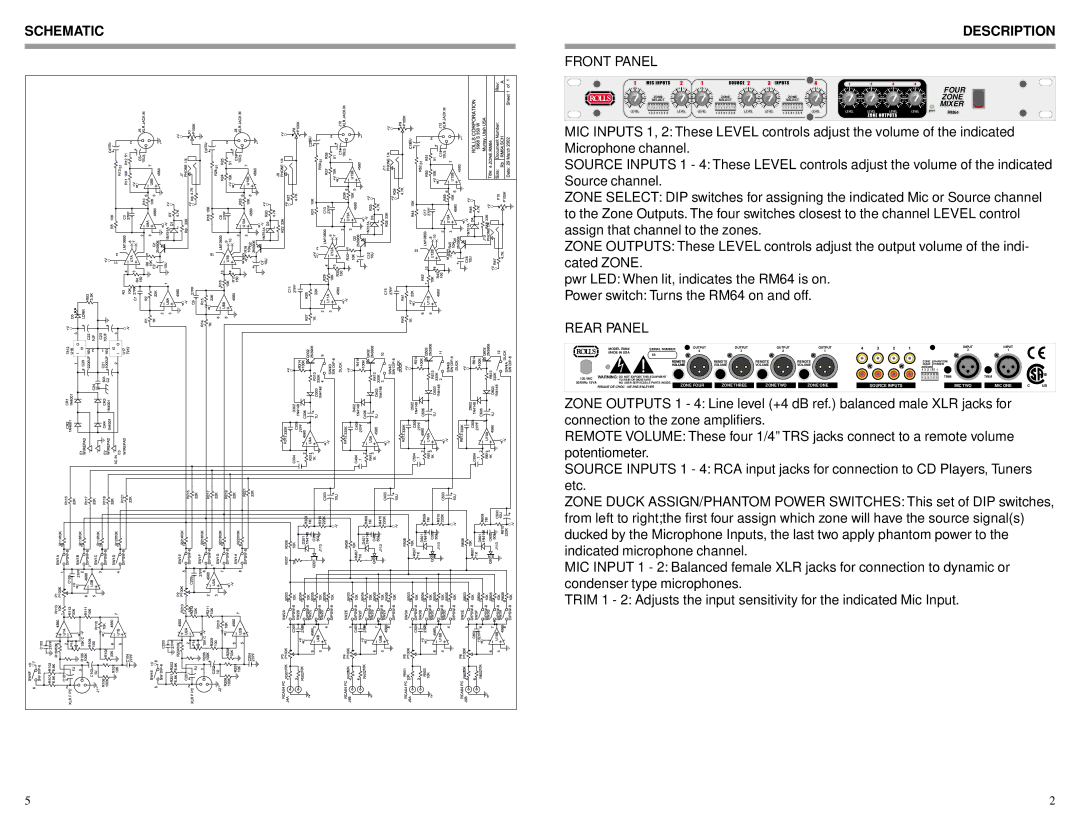
MIC INPUTS 1, 2: These LEVEL controls adjust the volume of the indicated Microphone channel.
SOURCE INPUTS 1 - 4: These LEVEL controls adjust the volume of the indicated Source channel.
ZONE SELECT: DIP switches for assigning the indicated Mic or Source channel to the Zone Outputs. The four switches closest to the channel LEVEL control assign that channel to the zones.
ZONE OUTPUTS: These LEVEL controls adjust the output volume of the indi- cated ZONE.
pwr LED: When lit, indicates the RM64 is on.
Power switch: Turns the RM64 on and off.
REAR PANEL
| MODEL RM64 | SERIAL NUMBER | OUTPUT | OUTPUT | OUTPUT | OUTPUT | 4 | 3 | 2 | 1 | INPUT | INPUT |
|
|
| MADE IN USA |
| 4 | 3 | 2 | 1 |
|
|
|
| 2 | 1 |
|
|
| 64- |
|
|
|
|
|
|
|
|
|
|
|
| |
|
|
|
|
|
|
|
|
|
|
|
|
|
| |
|
| REMOTE | REMOTE | REMOTE | REMOTE |
|
|
| ZONE | PHANTOM |
|
|
| |
|
| VOLUME | VOLUME | VOLUME | VOLUME |
|
|
| DUCK | POWER |
|
|
| |
|
|
|
|
|
|
|
|
|
| ASSIGN |
|
|
|
|
|
|
|
|
|
|
|
|
|
| 4 3 2 1 | 2 1 |
|
|
|
120 VAC | WARNING: DO NOT EXPOSE THIS EQUIPMENT |
|
|
|
|
|
|
| 1 2 3 4 | 5 6 TRIM | TRIM |
|
| |
TO RAIN OR MOISTURE |
|
|
|
|
|
|
|
|
|
|
|
| ||
50/60Hz 15VA | NO USER SERVICABLE PARTS INSIDE. | ZONE FOUR | ZONE THREE | ZONE TWO | ZONE ONE |
| SOURCE INPUTS |
| MIC TWO | MIC ONE | C | US | ||
| RISQUE DE CHOC - NE PAS ENLEVER |
|
| |||||||||||
ZONE OUTPUTS 1 - 4: Line level (+4 dB ref.) balanced male XLR jacks for connection to the zone amplifiers.
REMOTE VOLUME: These four 1/4” TRS jacks connect to a remote volume potentiometer.
SOURCE INPUTS 1 - 4: RCA input jacks for connection to CD Players, Tuners etc.
ZONE DUCK ASSIGN/PHANTOM POWER SWITCHES: This set of DIP switches, from left to right;the first four assign which zone will have the source signal(s) ducked by the Microphone Inputs, the last two apply phantom power to the indicated microphone channel.
MIC INPUT 1 - 2: Balanced female XLR jacks for connection to dynamic or condenser type microphones.
TRIM 1 - 2: Adjusts the input sensitivity for the indicated Mic Input.
2