CONNECTION |
|
|
|
| OPERATION |
|
|
|
|
|
|
|
|
|
|
|
|
|
|
|
|
|
|
|
|
|
|
|
|
|
|
|
|
|
|
Referring to the diagram above, connect microphones to the MIC INPUTs and apply phantom power where needed. Connect sources such as cassette players, CD players, AM/FM tuners, etc. to the RCA Source Inputs. Note which input each device is connected to as that input corresponds to its front panel Level control. Connect the XLR outputs to their respective zone amplifiers and speakers. The balanced signals are configured to pin 2 hot, pin 3 neutral, and pin 1 ground. For ground lifting it will be necessary to remove the connection to pin 1.
For Remote Volume operation, a
10K to 100K Ohm
Linear taper potentiometer
Sleeve
Tip
Ring
|
|
| ZONE |
|
|
|
|
|
| ZONE |
|
|
| ||||||
|
| SELECT |
|
|
|
| SELECT |
|
| ||||||||||
| 1 | 2 | 3 | 4 | 5 | 6 | 7 | 8 |
|
| 1 | 2 | 3 | 4 | 5 | 6 | 7 | 8 |
|
LEVEL | 1 2 3 4 1 2 3 4 | LEVEL | LEVEL | 1 2 3 4 1 2 3 4 | LEVEL | ||||||||||||||
|
|
|
| ||||||||||||||||
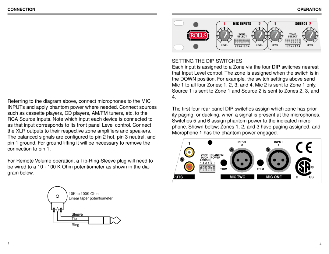
SETTING THE DIP SWITCHES
Each input is assigned to a Zone via the four DIP switches nearest that Input Level control. The zone is assigned when the switch is in the DOWN position. For example, the switch settings above send Mic 1 to all four Zones; 1, 2, 3, and 4. Mic 2 is sent to Zone 1 only. Source 1 is sent to Zone 1 and Source 2 is sent to Zones 2, 3, and 4.
The first four rear panel DIP switches assign which zone has prior- ity paging, or ducking, when a signal is present at the microphones. Switches 5 and 6 assign phantom power to the indicated micro- phone. Shown below; Zones 1, 2, and 3 have paging assigned, and Microphone 1 has the phantom power engaged.
1 | INPUT | INPUT |
|
|
2 | 1 |
|
| |
|
|
| ||
ZONE | PHANTOM |
|
|
|
DUCK | POWER |
|
|
|
ASSIGN |
|
|
|
|
4 3 2 1 | 2 1 |
|
|
|
1 2 3 4 | 5 6 TRIM | TRIM |
|
|
| MIC TWO | MIC ONE | C | US |
3 | 4 |