INTRODUCTION
Thank your for your purchase of the Rolls RM70 Mic/Source Selector. The RM70 is a single rack space audio mixer with three XLR inputs and four stereo RCA source inputs. It is ideal for aerobics studios, karaoke lounges, or audio visual applications.
INSPECTION
1. Unpack and inspect the RM70 box and package.
Your RM70 was carefully packed at the factory in a protective carton. Nonetheless, be sure to examine the unit and the carton for any signs of damage that may have occurred during shipping. If obvious physical damage is noticed, contact the carrier immediately to make a damage claim. We suggest saving the shipping carton and packing materials for safely transporting the unit in the future.
2.Please complete the Warranty Registration online at www.rolls.com , or complete the Warranty Card and return it to the factory.
DESCRIPTION
FRONT PANEL
-Vol 1 - 3: Adjust the volume of input from the XLR Mic inputs.
-Clip 1 - 3: Lights when the Mic Inputs signal reaches 3 dB below clipping.
-Tone 1 - 3: Adjusts the relative frequency content of the Mic signals. When turned counter- clockwise, the treble content is cut (3 dB down at 4 kHz). When turned clockwise, the bass content is cut (3 dB down at 300 Hz).
-Source 5: Stereo 1/8” (3.5mm) input jack.
-Source Select: Selects which source input signal is sent to the outputs. NOTE: Source number
3 is the signal sent to the Music On Hold output.
-Bass: Adjusts the low frequencies of the source inputs +/-12 dB at 100 Hz.
-Treble: Adjusts the high frequencies of the source inputs +/-12 dB at 11 kHz.
-Level: Adjusts the overall level from the main outputs.
-Pwr: Indicates that power has been applied to the RM70, and the unit is on.
REAR PANEL
-Mic 1 - 3: XLR inputs for dynamic or condenser microphones, or balanced line-level signals.
-Mic/Line switches: When pressed in - pads the XLR inputs by 35 dB.
-Mic/Loop Insert: 1/4” TRS insert jack (Tip-send, Ring-return) for inserting a signal processor or dynamics processor into the three Mic Input signal paths.
-DIP Switches: Described below from left to right:
•M/S; Mono/Stereo switch. When the switch is up, the unit is operating in Stereo mode and when down in Mono mode.
•T; Talkover. When the switch is down, Mic 1 is in talkover mode. When a signal is present at Mic 1, the sources are muted. The attack time is 10ms, and the release time is 1 second. The signals from the other Mic inputs are not muted.
•PHAN 3,2,1; Phantom power for the XLR inputs. When the indicated switch is down, 12 volts of phantom power is applied to that Mic input
-Source 1 - 4: RCA inputs for connection to stereo sources such as cassette players, CD play- ers, etc.
-Source Input 3 is the input for the Music On Hold.
-Music On Hold Level: Adjusts the level of signal from the Music On Hold output terminals.
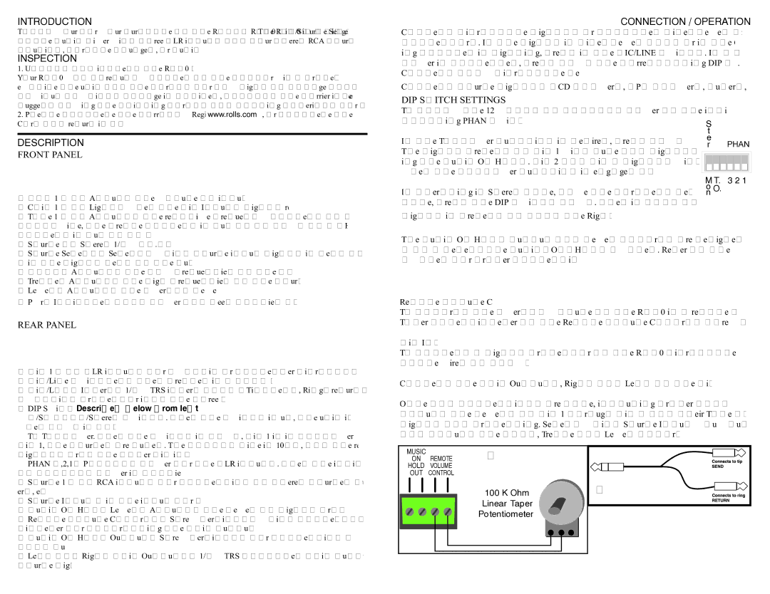
-Remote Volume Control: Screw terminals which connect to a 100K Ohm linear tapered poten- tiometer for controlling the main output level at a remote location.
-Music On Hold Output: Screw terminals for connection to a phone system for the music on hold function.
-Left and Right Main Outputs: 1/4” TRS balanced main outputs containing all Mic and selected source signals.
CONNECTION / OPERATION
Connect Microphone signals or balanced line-level signals to Mic 1 - 2 Input via the XLR connectors. If the signal is line-level (+4) or if the Clip LED indicator of the correspond- ing channel is lighting, press in the MIC/LINE switch. If a microphone requiring phantom power is connected, press down the corresponding DIP switch to apply phantom power. Connect only microphone level signals to Mic 3.
Connect source signals (CD players, MP3 players, tuners, etc.) to the Source Inputs 1 - 5.
DIP SWITCH SETTINGS
To apply the 12 volts of phantom power to the individual microphones, move the corre-
| sponding PHAN switch DOWN. | S | |
| | t | |
| If the Talkover function is desired, press down the DIP switch labeled T.O. | e | |
| r | PHAN |
| The signal present at Mic 1 will mute all signals at the Source Inputs, exclud- |
| | |
| ing the Music On Hold. Mic 2 and Mic 3 signals will still be sent to the outputs | | |
| when the talkover function is engaged and the sources are muted. | M T. | 3 2 1 |
| |
| If operating in Stereo Mode, move the farthest left DIP switch up, if in Mono | o O. | |
| n | |
| Mode, press the DIP switch down. When in Mono Mode - the mixed right/left | | |
| signal is present at both the Right and Left output jack. | | |
The Music On Hold output and level control are designed to send the signal from Source 3 to a telephone Music-On-Hold system. Refer to the owners manual of the telephone system for proper connection and adjustment.
Remote Volume Control
To control the overall volume of the RM70 in a remote location, wire a 100K ohm Linear Taper potentiometer to the Remote Volume Control screw terminals as shown in Figure 1.
Mic Insert
To connect a signal processor to the RM70 microphone signal(s), use an insert plug, or cable wired as shown in Figure 2.
Connect the Main Outputs, Right and Left to the distribution system or amplifiers.
Once all connections are made, including proper connection to a grounded AC outlet, adjust the levels of Mic 1 through Mic 3 and their Tone controls for the desired amounts of signal and processing. Select which Source Input you would like sent to the Main Outputs, and adjust the Bass, Treble and Level controls for their desired amounts.
MUSIC | | Figure 1. | |
ON | REMOTE | |
HOLD | VOLUME | | |
OUT | CONTROL | | |
| | 100 K Ohm | Figure 2. |
| | Linear Taper | |
| | Potentiometer | |