OPERATION
CONFIGURING THE 1/4” INPUT JACKS AS DIRECT OUTPUTS
The eight 1/4” Input jacks come from the factory configured as line inputs and are electrically mixed with the XLR jacks. They may be used together if desired. To configure a channel’s 1/4” jack as a Direct Out, first remove the RM83T lid.
For each channel there are dual
CONFIGURING THE 1/4” INPUT JACKS AS INSERTS
To configure a channel’s 1/4” jack as an Insert, first remove the RM83T lid and locate the corresponding channel’s dual
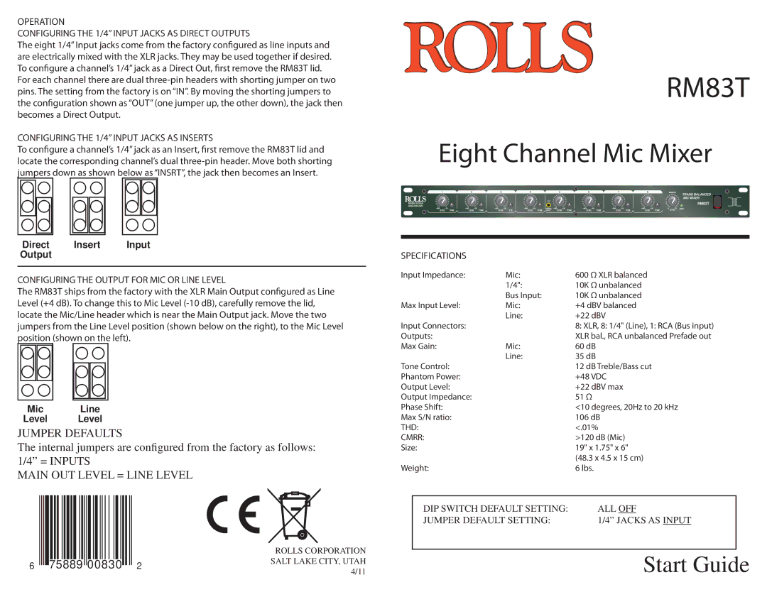
RM83T
Eight Channel Mic Mixer
1 | 2 | 3 | 4 |
| 5 | 6 | 7 | 8 |
| MASTER | TRANS BALANCED |
|
|
|
|
|
|
|
|
|
|
| |
|
|
|
| 1/8” |
|
|
|
|
|
| MIC MIXER |
MADE IN USA |
|
|
|
|
|
|
|
|
| RM83T | |
|
|
|
|
|
|
|
|
|
| ||
www.rolls.com |
|
|
|
|
|
|
|
|
|
| pwr |
+20 | +20 | +20 | +20 | STEREO | +20 | +20 | +20 | +20 | 0 | 10 | |
LEVEL TONE | LEVEL TONE | LEVEL TONE | LEVEL TONE | INPUT | LEVEL TONE | LEVEL TONE | LEVEL TONE | LEVEL TONE |
| LEVEL |
|
Direct Insert Input
Output
CONFIGURING THE OUTPUT FOR MIC OR LINE LEVEL
The RM83T ships from the factory with the XLR Main Output configured as Line Level (+4 dB). To change this to Mic Level
Mic Line
Level Level
JUMPER DEFAULTS
The internal jumpers are configured from the factory as follows: 1/4” = INPUTS
MAIN OUT LEVEL = LINE LEVEL
ROLLS CORPORATION
6 75889 00830 2SALT LAKE CITY, UTAH 4/11
SPECIFICATIONS
Input Impedance: | Mic: | 600 Ω XLR balanced |
| 1/4": | 10K Ω unbalanced |
| Bus Input: | 10K Ω unbalanced |
Max Input Level: | Mic: | +4 dBV balanced |
| Line: | +22 dBV |
Input Connectors: |
| 8: XLR, 8: 1/4" (Line), 1: RCA (Bus input) |
Outputs: |
| XLR bal., RCA unbalanced Prefade out |
Max Gain: | Mic: | 60 dB |
| Line: | 35 dB |
Tone Control: |
| 12 dB Treble/Bass cut |
Phantom Power: |
| +48 VDC |
Output Level: |
| +22 dBV max |
Output Impedance: |
| 51 Ω |
Phase Shift: |
| <10 degrees, 20Hz to 20 kHz |
Max S/N ratio: |
| 106 dB |
THD: |
| <.01% |
CMRR: |
| >120 dB (Mic) |
Size: |
| 19" x 1.75" x 6" |
|
| (48.3 x 4.5 x 15 cm) |
Weight: |
| 6 lbs. |
DIP SWITCH DEFAULT SETTING: | ALL OFF |
|
JUMPER DEFAULT SETTING: | 1/4” JACKS AS INPUT |
|
|
|
|
| Start Guide |
|