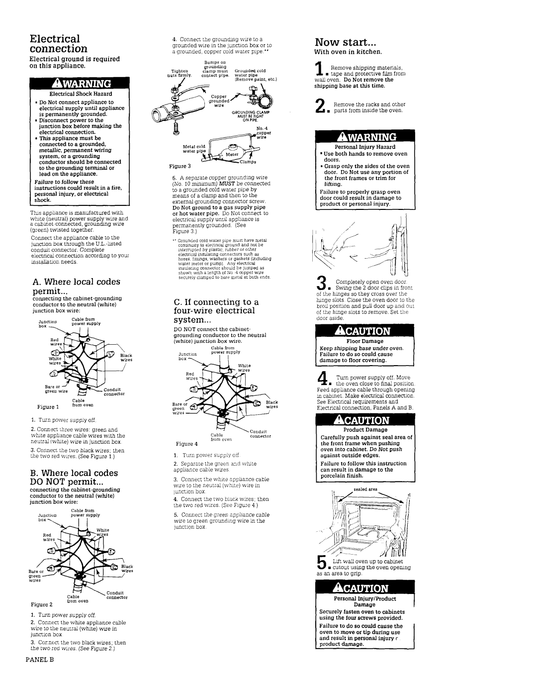
Electrical connection
Electrical ground is required on this appliance.
Electrical Shock Hazard
nDoNot connect applianceto electrical supply until appliance is permanently grounded.
mDisconnect power to the junction box before making the electrical connection.
lThis appliance must be connected to a grounded, metallic. permanent wiring system, or a grounding conductor should be connected to the grounding terminal or lead on the appliance.
Failure to follow these ~mtructions could result in a fire. personal injury, or electrical shock.
This appbance ISmanufactured with white (neutral) power supply wire an0 a
Connect the apphance cable to the ]uncttlonbox through the
electrical connection accordmg to youI mstallatmn needs
A. Where local codes
permit...
connecting the
Figure 1
1.Turn power supply off
2.Connect three wues: green and wtite apphance cable wires with the neutral (wh&) wue m junction box
3.Connect the two black wires; then the two red wues. (SeeFqure 1)
B. Where local codes
DO NOT permit...
connecting the
cannectar
Figure 2
1.Turn power supply off
2.Connen. the white apphance cable wire to the neutral (white) WLI~in ]unctmn box
3.Cornect the two black woes, then the two red wues. (SeeFigure 2 )
4.Connect the groundmg wLie to a grounded wue m the ]unctlon box or to a grounded, copper cold water pipe **
Figure 3
5.A separate copper groundmg wue (No. 10muumum) MUST be connected to a grounded cold water pipe by means of a clamp and then to the external groundmg connector screw. Do Not ground to a gas supply pipe or hot water oipe. Do Not connect to electrical sup$ until apphance 1s permanently grounded (See Figure 3 )
C. If connecting to a four-wire electrical system...
DO NOT connect the cabinet- grounding conductor to the neutral (white) junction box wire.
Cablefrom
Junction powel supply
I I
Figure 4
1.Turn power sugply orf
2.Separale the green and wtite apphance cable wues
3.Connect the while apphance cable wue to the neutral (white) wue m ]unchon box
4.Connect the two blacd wires, then the two red wires. (SeeF?gure4 )
5.Connect the green apphance cable wne to green groundmg wxe m the unction box
Now start...
With oven in kitchen.
1 Remove shippmg matenals, n taoe and Drotectlve film from
wall ovei. Do iot remove the shipping base at this time.
2 Remove the racks and other
. parts from mslde the oven.
Personal Injury Hazard
’Use both hands to remove oven doors.
lGrasp only the sides of the oven door. Do Not use any portion of the front frames or trim for lifimg.
Failure to properly grasp oven door could result in damage to oroduct or oersonal iniurv.
CJ rl
3 Completely open oven door
. Swmg the 2 door chps m front of the hmges so they cross over the hmge slots Close the oven door to the broil posltlon and pull door up and out of the hmge slots to remove. Set the door aslde.
Floor Damage |
| |
Keep dipping | base under oven. |
|
Failure to do so could cause |
| |
damage to floor covering. | I | |
4 Turn power supply off. Move m the oven close to final posmon
Feed apphance cable through openmg m cabmet. Make electrical connenlon SeeElectrical requirements and Electrical connection, Panels A and B.
Product Damage
Carefully push against seal area 01 the front frame when pushing oven into cabinet. Do Not push against outside edges.
Failure to follow this instruction can result in damage to the porcelain finish.
bft wall oven up to cabmet
. cutout using the oven opemng as an area to grip.
Personal Injury/Product
Securely fasten oven to cabinets using the four screws provided.
Failure to do so could cause the oven to move or tip during use and result in oersonal iniurv r
product damage. . . I
