Rosewill RGS-1024 Identifying External Components, Front Panel, Rear Panel, LED Indicators

Models: RGS-1024

1 16
Download 16 pages 26.09 Kb
Page 12
Image 12
Chapter 3. Identifying External Components

24-Port Gigabit Ethernet Switch RGS-1024

User Manual


Chapter 3. Identifying External Components

This Chapter describes the front panel, rear panel and LED indicators of the Switch.

3.1 Front Panel

The front panel of the RGS-1024 consists of switch LED indicators, 24 10/100/1000Mbps RJ-45 ports.

Figure 3-1 RGS-1024 Switch Front Panel sketch
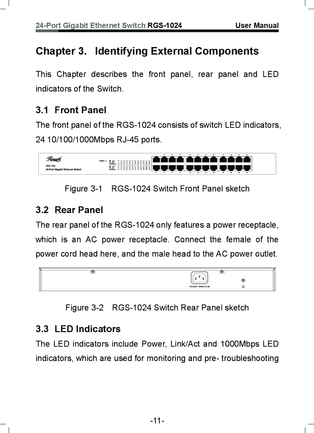
3.2 Rear Panel

The rear panel of the RGS-1024 only features a power receptacle, which is an AC power receptacle. Connect the female of the power cord head here, and the male head to the AC power outlet.

Figure 3-2 RGS-1024 Switch Rear Panel sketch

3.3 LED Indicators

The LED indicators include Power, Link/Act and 1000Mbps LED indicators, which are used for monitoring and pre- troubleshooting

-11-

Page 12
Image 12
Rosewill RGS-1024 user manual Identifying External Components, Front Panel, Rear Panel, LED Indicators