| User Manual | |
|
|
|
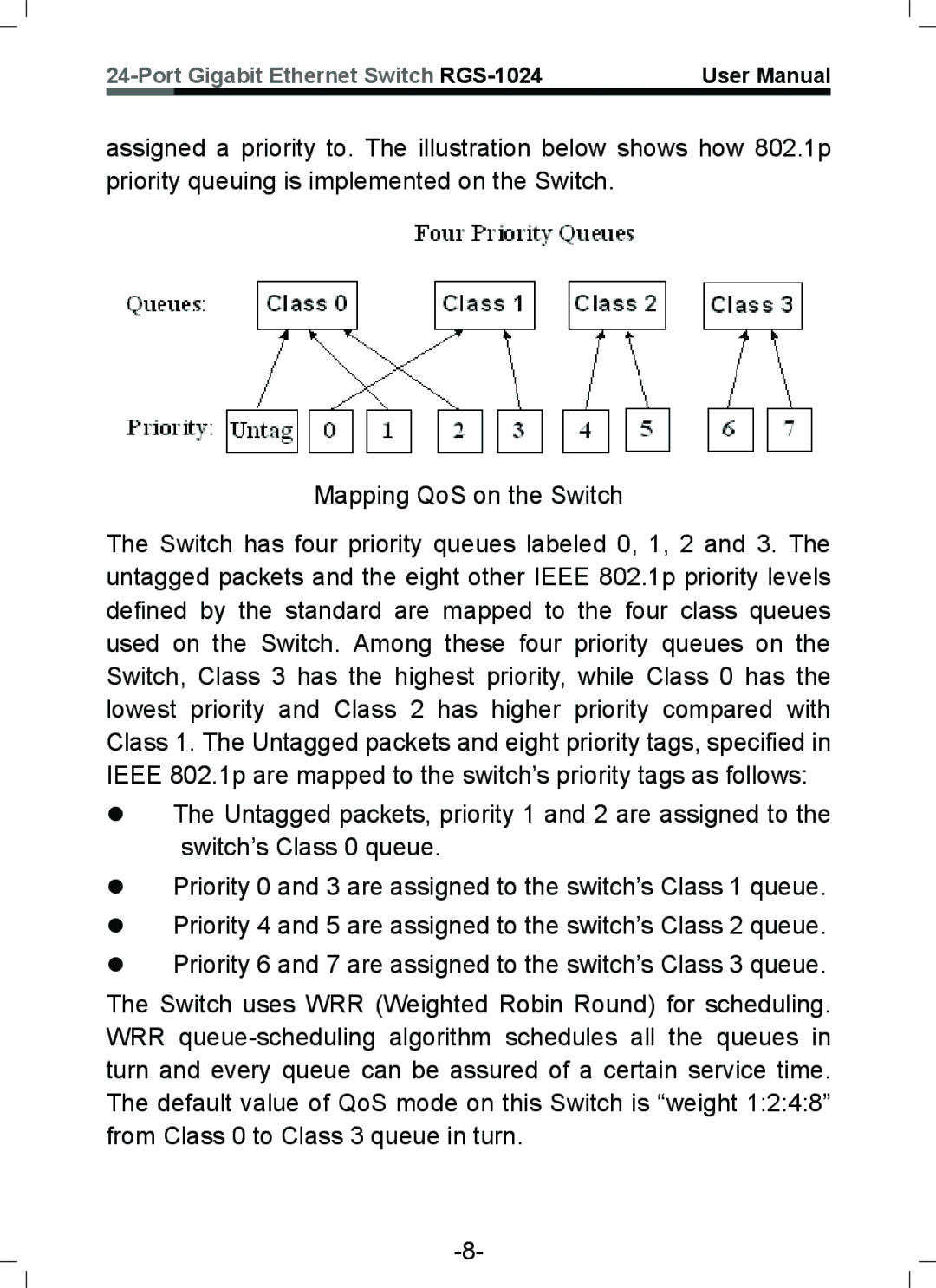
assigned a priority to. The illustration below shows how 802.1p priority queuing is implemented on the Switch.
Mapping QoS on the Switch
The Switch has four priority queues labeled 0, 1, 2 and 3. The untagged packets and the eight other IEEE 802.1p priority levels defined by the standard are mapped to the four class queues used on the Switch. Among these four priority queues on the Switch, Class 3 has the highest priority, while Class 0 has the lowest priority and Class 2 has higher priority compared with Class 1. The Untagged packets and eight priority tags, specified in IEEE 802.1p are mapped to the switch’s priority tags as follows:
zThe Untagged packets, priority 1 and 2 are assigned to the switch’s Class 0 queue.
zPriority 0 and 3 are assigned to the switch’s Class 1 queue.
zPriority 4 and 5 are assigned to the switch’s Class 2 queue.
zPriority 6 and 7 are assigned to the switch’s Class 3 queue.
The Switch uses WRR (Weighted Robin Round) for scheduling. WRR