Manuals
/
Rosewill
/
Computer Equipment
/
Network Card
Rosewill
RNWA-PoE-100
user manual
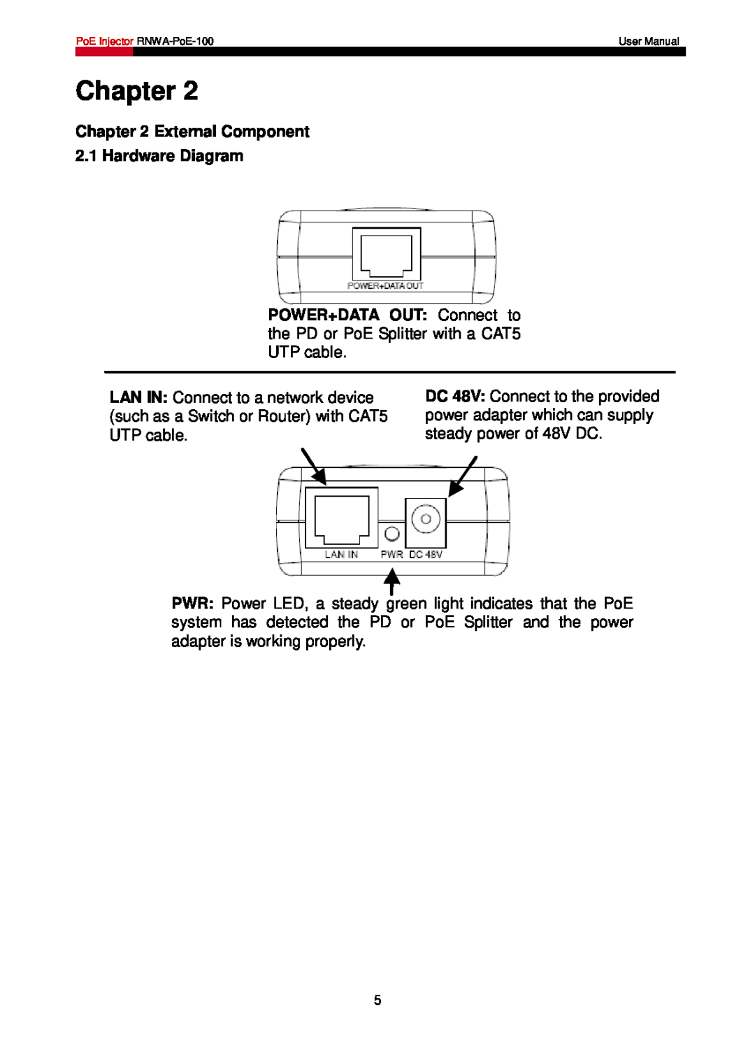
External Component 2.1 Hardware Diagram, Chapter
Models:
RNWA-PoE-100
1
6
9
9
Download
9 pages
20.22 Kb
2
3
4
5
6
7
8
9
Wired Setup
Features
Page 6
Image 6
Page 5
Page 7
Page 6
Image 6
Page 5
Page 7
Contents
PoE Injector RNWA-PoE-100
User Manual
FCC STATEMENT
CE Mark Warning
CHAPTER 1 OVERVIEW
Table of Content
CHAPTER 3 CONNECTING THE POE INJECTOR……………………………………6
CHAPTER 2 EXTERNAL COMPONENT………………………………………………..5
1.1 Package Content
Chapter
Chapter 1 Overview
1.2 Features
1.3 Product Specification Normal
Environmental and Physical
Chapter 2 External Component 2.1 Hardware Diagram
Chapter 3 Connecting the PoE Injector
3.1 Wired Setup
Call Center
3.2 Wireless Setup
Let us know
Rosewill Support techsupport@rosewill.com
Top
Page
Image
Contents