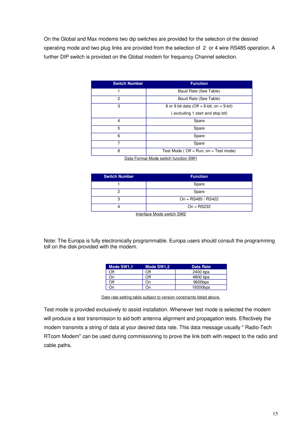
On the Global and Max modems two dip switches are provided for the selection of the desired operating mode and two plug links are provided from the selection of 2 or 4 wire RS485 operation. A further DIP switch is provided on the Global modem for frequency Channel selection.
Switch Number | Function |
|
|
1 | Baud Rate (See Table) |
|
|
2 | Baud Rate (See Table) |
|
|
3 | 8 or 9 bit data (Off = |
| ( excluding 1 start and stop bit) |
|
|
4 | Spare |
|
|
5 | Spare |
|
|
6 | Spare |
|
|
7 | Spare |
|
|
8 | Test Mode ( Off = Run, on = Test mode) |
|
|
Data Format Mode switch function SW1 | |
Switch Number |
| Function |
|
|
|
1 |
| Spare |
|
|
|
2 |
| Spare |
|
|
|
3 |
| On = RS485 / RS422 |
|
|
|
4 |
| On = RS232 |
|
|
|
| Interface Mode switch SW2 | |
Note: The Europa is fully electronically programmable. Europa users should consult the programming toll on the disk provided with the modem.
Mode SW1,1
Off
Mode SW1,2
Off
Data Rate
2400 bps
On | Off | 4800 bps |
Off | On | 9600bps |
On | On | 19200bps |
Date rate setting table subject to version constraints listed above.
Test mode is provided exclusively to assist installation. Whenever test mode is selected the modem will produce a test transmission to aid both antenna alignment and propagation tests. Effectively the modem transmits a string of data at your desired data rate. This data message usually "
15