Wiring example
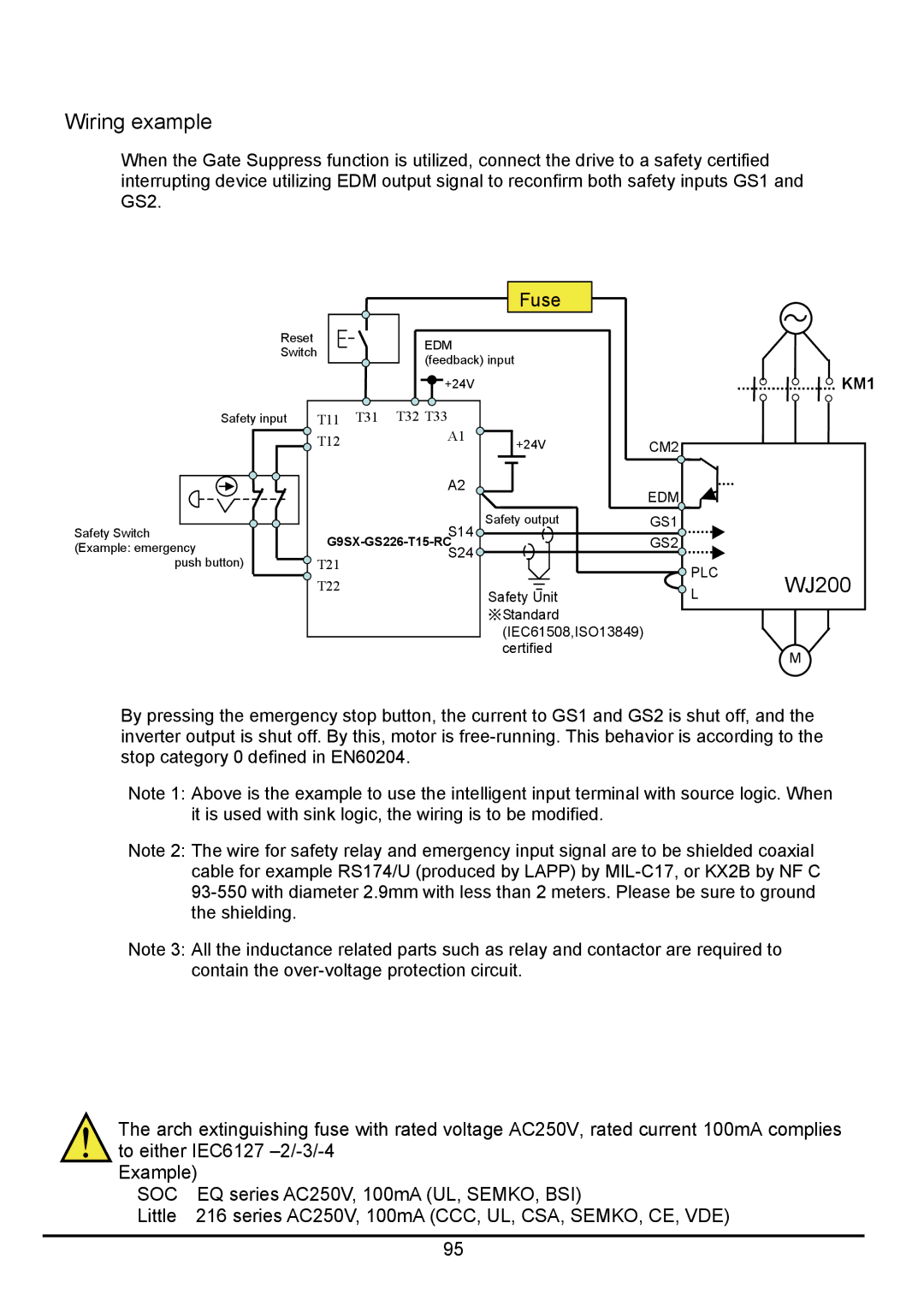
When the Gate Suppress function is utilized, connect the drive to a safety certified interrupting device utilizing EDM output signal to reconfirm both safety inputs GS1 and GS2.
|
|
|
| Fuse |
|
|
Reset |
|
| EDM |
|
|
|
Switch |
|
|
|
| ||
| (feedback) input |
|
| |||
|
|
|
|
| ||
|
|
| +24V |
|
| KM1 |
Safety input | T11 | T31 | T32 T33 |
|
|
|
| T12 |
| A1 | +24V | CM2 |
|
|
|
|
| |||
|
|
|
|
| ||
|
|
| A2 |
| EDM |
|
|
|
|
|
|
| |
Safety Switch |
|
| S14 | Safety output | GS1 |
|
|
|
|
|
| ||
(Example: emergency |
| GS2 |
| |||
push button) | T21 |
|
|
| PLC | WJ200 |
| T22 |
|
|
| ||
|
|
| Safety Unit | L | ||
|
|
|
|
| ||
|
|
|
| ※Standard |
|
|
|
|
|
| (IEC61508,ISO13849) |
|
|
|
|
|
| certified |
| M |
|
|
|
|
|
| |
By pressing the emergency stop button, the current to GS1 and GS2 is shut off, and the inverter output is shut off. By this, motor is
Note 1: Above is the example to use the intelligent input terminal with source logic. When it is used with sink logic, the wiring is to be modified.
Note 2: The wire for safety relay and emergency input signal are to be shielded coaxial cable for example RS174/U (produced by LAPP) by
Note 3: All the inductance related parts such as relay and contactor are required to contain the
The arch extinguishing fuse with rated voltage AC250V, rated current 100mA complies to either IEC6127
Example)
SOC | EQ series AC250V, 100mA (UL, SEMKO, BSI) |
Little | 216 series AC250V, 100mA (CCC, UL, CSA, SEMKO, CE, VDE) |
|
|
| 95 |