(When safety switch or EDM switch is turned off, the intelligent input and output terminal assigned on will be set as "no" function, and contact will remain normally off.)
Always use both inputs to disable the drive. If for any reason only one channel is opened, the drive output is stopped but the EDM output is not activated. In this case the Safe Disable input wiring must be checked.
Installation
According to the safety standard listed above, please install referring to the example. Please be sure to use the both GS1 and GS2, and construct the system that GS1 andGS2 are both turned off when safety input is given to the inverter.
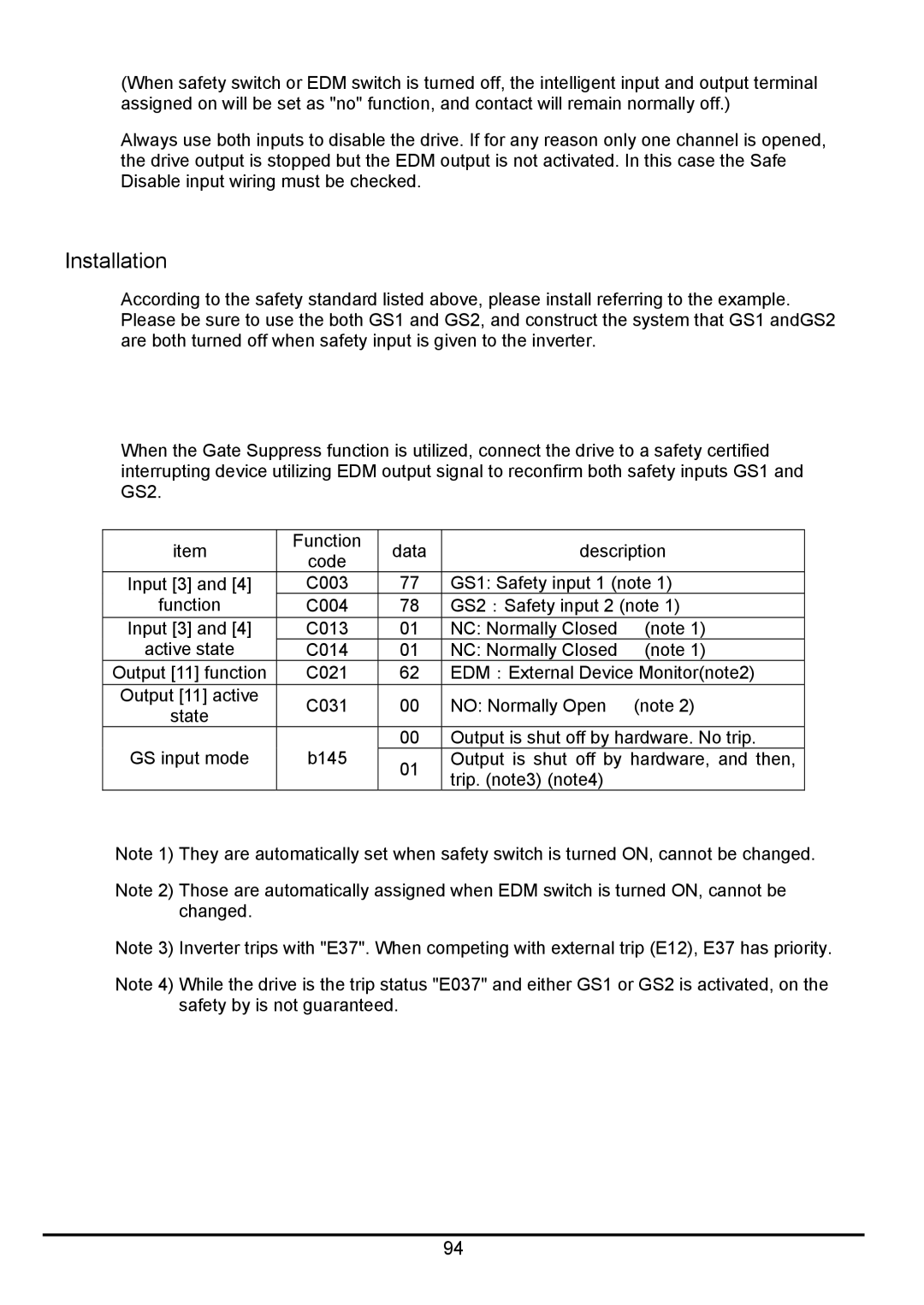
When the Gate Suppress function is utilized, connect the drive to a safety certified interrupting device utilizing EDM output signal to reconfirm both safety inputs GS1 and GS2.
item | Function | data | description | ||
code | |||||
|
|
|
| ||
Input [3] and [4] | C003 | 77 | GS1: Safety input 1 (note 1) | ||
function | C004 | 78 | GS2:Safety input 2 (note 1) | ||
Input [3] and [4] | C013 | 01 | NC: Normally Closed | (note 1) | |
active state | C014 | 01 | NC: Normally Closed | (note 1) | |
Output [11] function | C021 | 62 | EDM:External Device Monitor(note2) | ||
Output [11] active | C031 | 00 | NO: Normally Open | (note 2) | |
state | |||||
|
|
|
| ||
GS input mode | b145 | 00 | Output is shut off by hardware. No trip. | ||
01 | Output is shut off by hardware, and then, | ||||
|
| trip. (note3) (note4) |
| ||
|
|
|
| ||
Note 1) They are automatically set when safety switch is turned ON, cannot be changed.
Note 2) Those are automatically assigned when EDM switch is turned ON, cannot be changed.
Note 3) Inverter trips with "E37". When competing with external trip (E12), E37 has priority.
Note 4) While the drive is the trip status "E037" and either GS1 or GS2 is activated, on the safety by is not guaranteed.
94