Using Intelligent Output Terminals |
| ||||||
Run Signal |
|
|
|
|
| ||
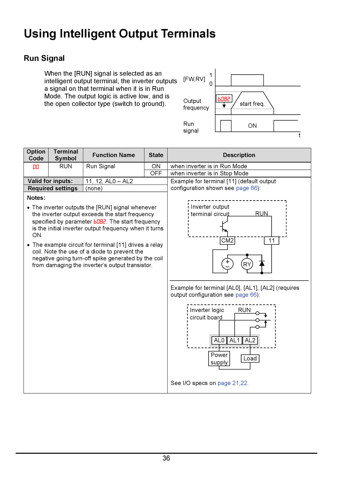
When the [RUN] signal is selected as an |
| 1 |
| ||||
intelligent output terminal, the inverter outputs [FW,RV] |
| ||||||
a signal on that terminal when it is in Run |
| 0 |
| ||||
|
|
| |||||
Mode. The output logic is active low, and is | Output | B082 |
| ||||
the open collector type (switch to ground). | start freq. | ||||||
frequency |
| ||||||
|
|
|
|
|
| ||
|
|
|
| Run |
| ON | |
|
|
|
| signal |
| t | |
|
|
|
|
|
| ||
Option | Terminal | Function Name | State |
| Description | ||
Code | Symbol |
| |||||
|
|
|
|
| |||
00 | RUN | Run Signal | ON | when inverter is in Run Mode | |||
|
|
| OFF | when inverter is in Stop Mode | |||
|
| 11, 12, AL0 – AL2 |
| Example for terminal [11] (default output | |||
|
| (none) |
| configuration shown see page 66): | |||
Notes: |
|
|
|
|
|
|
|
|
|
|
|
|
|
|
|
• The inverter outputs the [RUN] signal whenever | Inverter output |
| RUN |
|
| ||||||||||
the inverter output exceeds the start frequency | terminal circuit |
|
|
|
|
| |||||||||
specified by parameter B082. The start frequency |
|
|
|
|
|
|
|
|
|
|
|
|
|
|
|
|
|
|
|
|
|
|
|
|
|
|
|
|
|
| |
is the initial inverter output frequency when it turns |
|
|
|
|
|
|
|
|
|
|
|
|
|
|
|
|
|
|
|
|
|
|
|
|
|
|
|
|
|
| |
ON. |
|
|
|
|
|
|
|
|
|
|
|
|
|
|
|
|
| CM2 |
|
|
|
| 11 |
| |||||||
• The example circuit for terminal [11] drives a relay |
|
|
|
| |||||||||||
|
|
|
|
|
|
|
|
|
|
|
|
|
|
| |
coil. Note the use of a diode to prevent the |
|
|
|
|
|
|
|
|
|
|
|
|
|
|
|
|
|
|
|
|
|
|
|
|
|
|
|
|
|
| |
negative going |
|
|
|
|
|
|
| RY |
|
|
|
|
|
| |
|
|
|
|
|
|
|
|
|
|
|
|
| |||
from damaging the inverter’s output transistor. |
|
|
|
|
|
|
|
|
|
|
|
| |||
|
|
|
|
|
|
|
|
| |||||||
|
|
|
|
|
|
|
|
| |||||||
|
|
|
|
|
|
|
|
|
|
|
|
|
|
|
|
|
|
|
|
|
|
|
|
|
|
|
|
|
|
|
|
Example for terminal [AL0], [AL1], [AL2] (requires output configuration see page 66):
Inverter logic | RUN |
circuit board |
|
AL0 | AL1 AL2 |
|
|
|
|
|
Power |
|
|
| |
| Load | |||
supply |
| |||
|
|
| ||
|
|
|
|
|
See I/O specs on page 21,22.
36