CE-EMC Installation Guidelines
You are required to satisfy the EMC directive (2004/108/EC) when using an WJ200 inverter in an EU country.
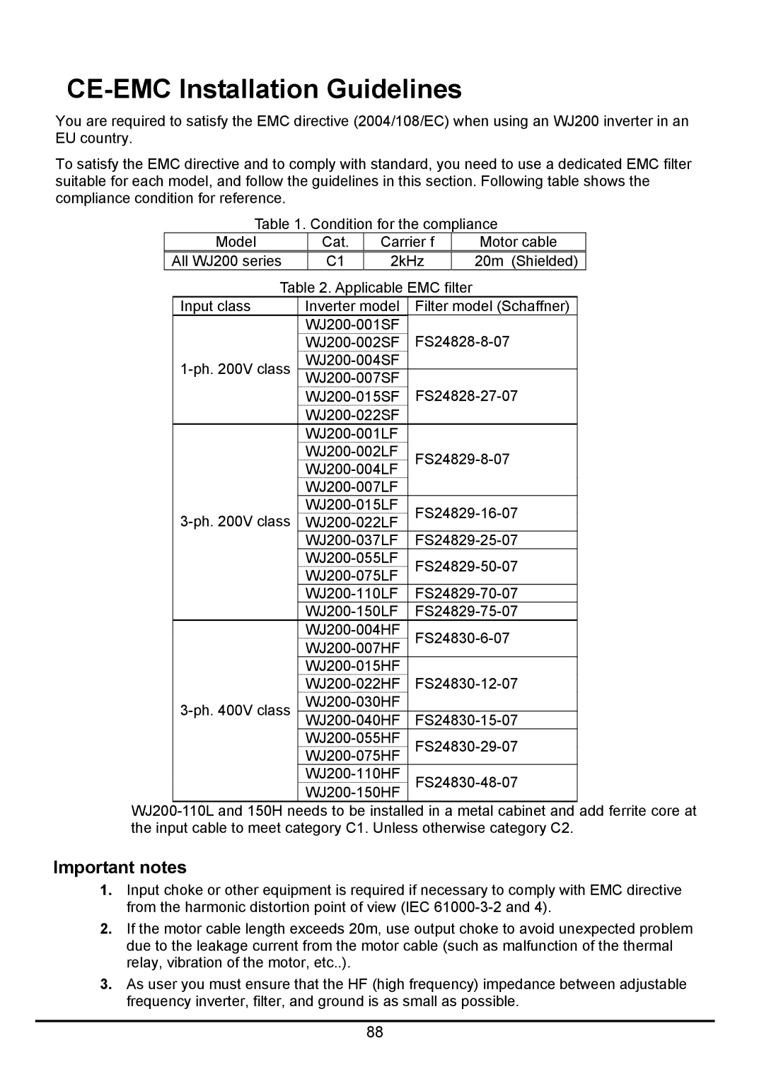
To satisfy the EMC directive and to comply with standard, you need to use a dedicated EMC filter suitable for each model, and follow the guidelines in this section. Following table shows the compliance condition for reference.
Table 1. Condition for the compliance
| Model |
| Cat. | Carrier f |
| Motor cable | ||
All WJ200 series |
| C1 | 2kHz |
| 20m (Shielded) | |||
| Table 2. Applicable EMC filter |
|
| |||||
| Input class | Inverter model | Filter model (Schaffner) |
| ||||
|
|
| ||||||
|
|
| ||||||
|
|
|
|
| ||||
|
| |||||||
|
|
| ||||||
|
|
| ||||||
|
|
|
|
|
| |||
|
|
|
|
|
| |||
|
|
| ||||||
|
|
| ||||||
|
|
|
|
|
| |||
|
|
|
|
|
| |||
|
| |||||||
|
| |||||||
|
|
|
|
| ||||
|
|
| ||||||
|
|
| ||||||
|
|
| ||||||
|
|
|
|
|
| |||
|
|
| ||||||
|
|
| ||||||
|
|
| ||||||
|
|
|
|
|
| |||
|
|
|
|
|
| |||
|
|
| ||||||
|
|
|
|
| ||||
|
| |||||||
|
|
| ||||||
|
|
| ||||||
|
|
|
|
|
| |||
|
|
| ||||||
|
|
|
|
|
| |||
Important notes
1.Input choke or other equipment is required if necessary to comply with EMC directive from the harmonic distortion point of view (IEC
2.If the motor cable length exceeds 20m, use output choke to avoid unexpected problem due to the leakage current from the motor cable (such as malfunction of the thermal relay, vibration of the motor, etc..).
3.As user you must ensure that the HF (high frequency) impedance between adjustable frequency inverter, filter, and ground is as small as possible.
88
