WJ200 Series Inverter Quick Reference Guide
Page
UL→ Cautions, Warnings and Instructions
Marking Requirements
Terminal symbols and Screw size
Fuse Sizes
5AT 123 45A-001 1005
Inverter Specification Label
Model-specific tables for 200V and 400V class inverters
WJ200 Inverter Specifications
WJ200 Inverter Specifications, …
WJ200 inverters, 400V models
Derating
GFI
Basic System Description
Inverter +
Motor Output
Determining Wire and Fuse Sizes
Allowable current
T1 V/T2 W/T3 L1 S/L2 T/L3 U/T1 V/T2 W/T3
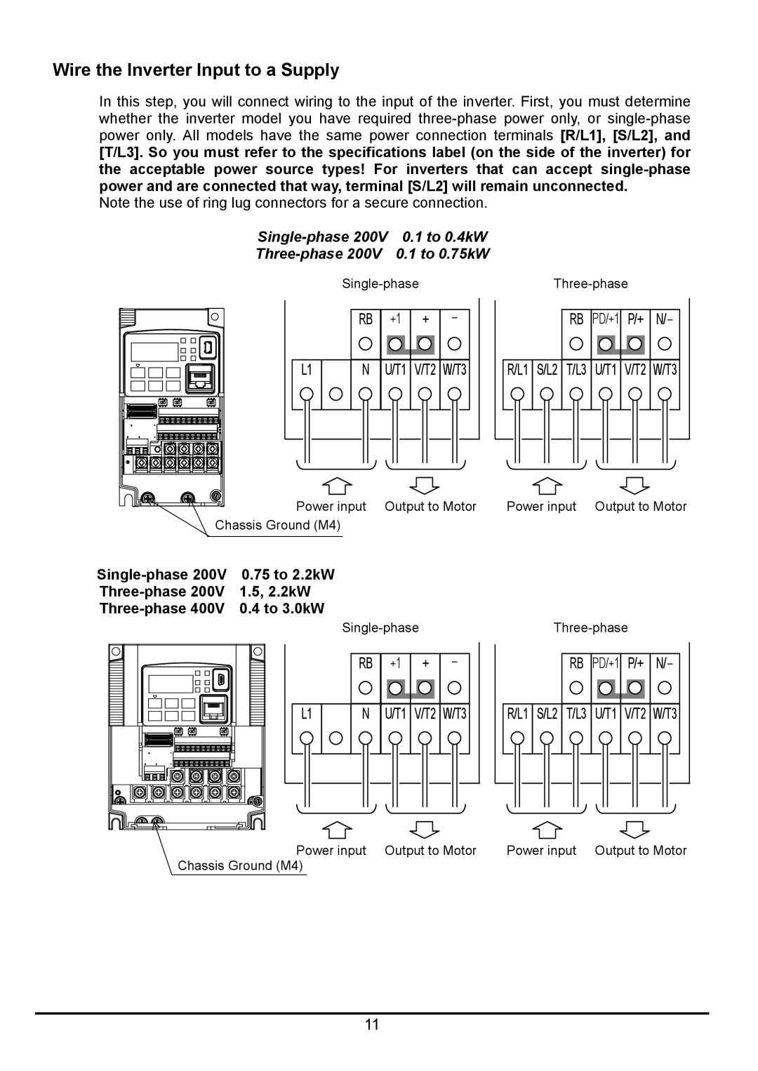
Wire the Inverter Input to a Supply
RB PD/+1 P/+
Three-phase 200V 11kW Three-phase 400V 11, 15kW
Key and Indicator Legend
Using the Front Panel Keypad
Power LED Alarm LED
Keypad Navigation Map
Keys, Modes, and Parameters
PRG LED
Group F
Group d
Save
Group a
F001
Key
GND
Connecting to PLCs and Other Devices
Motor
Example Wiring Diagram
Pulse
Control Logic Signal Specifications
Train
Output Input
SP, SN
Wiring sample of control logic terminal sink logic
Sink/source logic of intelligent input terminals
Wire size for control and relay terminals
Recommended ferrule
Intelligent Inputs
Intelligent Terminal Listing
Intelligent Outputs
Sink logic connection
Using Intelligent Input Terminals
Source logic connection
WJ200
Sinking Inputs, Internal Supply
Sourcing Inputs, Internal Supply
Sourcing Inputs, External Supply
Sinking Inputs, External Supply
OFF
Inserting
Option Terminal Code Symbol Function Name State Description
Forward Run/Stop and Reverse Run/Stop Commands
Multi-Speed Select ~Binary Operation
Required settings
FW,RV
Two Stage Acceleration and Deceleration
2CH
Unattended Start Protection
Option Terminal Function Name State Description Code Symbol
USP
Reset Inverter
Run Signal
Using Intelligent Output Terminals
Code Symbol
Option Terminal Function Name
Settings
Frequency Arrival Signals
Required
FA3/FA5
FA2/FA4
Stop
Alarm Signal
Trip
During normal operation
AM H O OI L
Analog Input Operation
AM H O OI
Other Analog Input-related topics
SN 7 6 5 4 3 2 1 L PLC P24
Pulse Train Input Operation
Analog Output Operation
AM signal offset and gain are adjustable, as indicated below
Monitoring functions
D007
D006
D008
D009
D030
D029
D050
D060
Main Profile Parameters
Standard Functions
A220
A015
A241
A021 ~ A035
A043
A242
A243
A044
A059
A058
A061
A261
A073
A072
A074
A075
A292
A092
A093
A293
A132
A131
A141
A142
A157
A156
A161
A162
Fine Tuning Functions
B212
B012
B013
B213
B026
B025
B027
B028
B038
B037
B039
B040
B061
B060
B062
B063
B088
B087
B089
B090
B097
B096
B100
B101
B134
B133
B145
B150
Intelligent Terminal Functions
C030
C028
C031
C032
C052
C047
C053
C054
C077
C076
C078
C081
C103
C102
C104
C105
C148
C147
C149
C150
FWD, REV
Anlg
Pidc
DWN
SF2
SF1
SF3
SF4
255
Run Signal When the inverter is in Run Mode
LOG2
LOG1
LOG3
MO1
C039
MO2
MO3
Motor Constants Functions
PM Motor Constants Functions
H113
H112
H116
H117
Expansion Card Functions
P044
P041
P045
P046
P073
P072
P075
P077
Trip History and Inverter Status
Monitoring Trip Events, History, & Conditions
Error Name Causes Code
Error Codes
E37
Error Name Descriptions Code
Restoring Factory Default Settings
Other indication
Important notes
CE-EMC Installation Guidelines
Page
Page
Metal plate earth
Installation for WJ200 series example of SF models
Hitachi EMC Recommendations
Introduction
Functional Safety Certification in Progress
Stop Category defined in EN60204-1
How it works
Installation
Wiring example
OFF
G9SX
GS9A
NE1A