|
|
|
|
|
|
|
|
|
|
|
|
|
|
|
|
|
|
| Option |
|
| Terminal |
|
| Function Name |
|
|
| Description |
|
|
| |||
| Code |
|
| Symbol |
|
|
|
|
|
|
|
| |||||
|
|
|
|
|
|
|
|
|
|
|
|
|
|
|
| ||
|
|
|
|
|
|
|
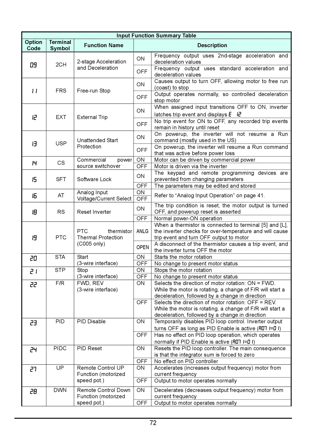
| ON | Frequency output | uses | acceleration | and |
| ||||
| 09 |
|
| 2CH |
|
| deceleration values |
|
|
|
|
| |||||
|
|
|
|
|
|
|
|
|
|
| |||||||
|
|
|
| and Deceleration |
| OFF | Frequency output | uses | standard | acceleration | and |
| |||||
|
|
|
|
|
|
|
|
| |||||||||
|
|
|
|
|
|
|
|
|
|
| deceleration values |
|
|
|
|
| |
|
|
|
|
|
|
|
|
|
|
|
|
|
|
|
|
| |
|
|
|
|
|
|
|
|
|
|
| ON | Causes output to turn OFF, allowing motor to free run |
| ||||
| 11 |
|
| FRS |
| (coast) to stop |
|
|
|
|
| ||||||
|
|
|
|
|
|
|
|
|
| ||||||||
|
|
|
| OFF | Output operates normally, so controlled deceleration |
| |||||||||||
|
|
|
|
|
|
|
|
|
|
|
| ||||||
|
|
|
|
|
|
|
|
|
|
| stop motor |
|
|
|
|
| |
|
|
|
|
|
|
|
|
|
|
|
|
|
|
|
|
| |
|
|
|
|
|
|
|
|
|
|
| ON | When assigned input transitions OFF to ON, inverter |
| ||||
| 12 |
|
| EXT |
| External Trip |
|
|
| latches trip event and displays E 12 |
|
|
| ||||
|
|
|
|
|
|
|
|
|
|
| |||||||
|
|
|
|
|
|
| OFF | No trip event for ON to OFF, any recorded trip events |
| ||||||||
|
|
|
|
|
|
|
|
|
|
|
| ||||||
|
|
|
|
|
|
|
|
|
|
| remain in history until reset |
|
|
| |||
|
|
|
|
|
|
|
|
|
|
|
|
|
|
| |||
|
|
|
|
|
|
| Unattended Start |
| ON | On powerup, the | inverter will not | resume a | Run |
| |||
| 13 |
|
| USP |
|
| command (mostly used in the US) |
|
|
| |||||||
|
|
|
|
|
|
|
|
| |||||||||
|
|
|
| Protection |
|
|
| OFF | On powerup, the inverter will resume a Run command |
| |||||||
|
|
|
|
|
|
|
|
|
|
| |||||||
|
|
|
|
|
|
|
|
|
|
| that was active before power loss |
|
|
| |||
|
|
|
|
|
|
|
|
|
|
|
|
|
|
| |||
| 14 |
|
| CS |
| Commercial | power |
| ON | Motor can be driven by commercial power |
|
| |||||
|
|
|
| source switchover |
| OFF | Motor is driven via the inverter |
|
|
| |||||||
|
|
|
|
|
|
|
|
|
|
| |||||||
|
|
|
|
|
|
|
|
|
|
| ON | The keypad and | remote programming devices | are |
| ||
| 15 |
|
| SFT |
| Software Lock |
| prevented from changing parameters |
|
|
| ||||||
|
|
|
|
| OFF |
|
|
| |||||||||
|
|
|
|
|
|
|
|
|
|
| The parameters may be edited and stored |
|
| ||||
| 16 |
|
| AT |
| Analog Input |
|
|
| ON | Refer to “Analog Input Operation” on page 41. |
|
| ||||
|
|
|
| Voltage/Current Select |
| OFF |
|
| |||||||||
|
|
|
|
|
|
|
| The trip condition is reset, the motor output is turned |
| ||||||||
|
|
|
|
|
|
|
|
|
|
| ON |
| |||||
| 18 |
|
| RS |
| Reset Inverter |
| OFF, and powerup reset is asserted |
|
|
| ||||||
|
|
|
|
| OFF |
|
|
| |||||||||
|
|
|
|
|
|
|
|
|
|
| Normal |
|
|
| |||
|
|
|
|
|
|
|
|
|
|
|
| When a thermistor is connected to terminal [5] and [L], |
| ||||
|
|
|
|
|
|
| PTC | thermistor |
| ANLG | the inverter checks for |
| |||||
| 19 |
|
| PTC |
| Thermal Protection |
|
| trip event and turn OFF output to motor |
|
| ||||||
|
|
|
|
|
|
| (C005 only) |
|
|
| OPEN | A disconnect of the thermistor causes a trip event, and |
| ||||
|
|
|
|
|
|
|
|
|
|
|
| the inverter turns OFF the motor |
|
|
| ||
| 20 |
|
| STA |
| Start |
|
|
| ON | Starts the motor rotation |
|
|
|
| ||
|
|
|
|
|
|
|
| OFF | No change to present motor status |
|
|
| |||||
| 21 |
|
| STP | Stop |
|
|
| ON | Stops the motor rotation |
|
|
|
| |||
|
|
|
|
|
|
|
| OFF | No change to present motor status |
|
|
| |||||
| 22 |
|
| F/R | FWD, REV |
|
|
| ON | Selects the direction of motor rotation: ON = FWD. |
|
| |||||
|
|
|
|
|
|
|
|
| While the motor is rotating, a change of F/R will start a |
| |||||||
|
|
|
|
|
|
|
|
|
|
|
| deceleration, followed by a change in direction |
|
| |||
|
|
|
|
|
|
|
|
|
|
| OFF | Selects the direction of motor rotation: OFF = REV. |
|
| |||
|
|
|
|
|
|
|
|
|
|
|
| While the motor is rotating, a change of F/R will start a |
| ||||
|
|
|
|
|
|
|
|
|
|
|
| deceleration, followed by a change in direction |
|
| |||
| 23 |
|
| PID | PID Disable |
|
|
| ON | Temporarily disables PID loop control. Inverter output |
| ||||||
|
|
|
|
|
|
|
|
|
|
|
| turns OFF as long as PID Enable is active (A071=01) |
| ||||
|
|
|
|
|
|
|
|
|
|
| OFF | Has no effect on PID loop operation, which operates |
| ||||
|
|
|
|
|
|
|
|
|
|
|
| normally if PID Enable is active (A071=01) |
|
| |||
| 24 |
|
| PIDC |
| PID Reset |
|
|
| ON | Resets the PID loop controller. The main consequence |
| |||||
|
|
|
|
|
|
|
|
|
|
|
| is that the integrator sum is forced to zero |
|
| |||
|
|
|
|
|
|
|
|
|
|
| OFF | No effect on PID controller |
|
|
| ||
| 27 |
|
| UP |
| Remote Control UP |
| ON | Accelerates (increases output frequency) motor from |
| |||||||
|
|
|
|
|
|
| Function (motorized |
|
| current frequency |
|
|
|
|
| ||
|
|
|
|
|
|
| speed pot.) |
|
|
| OFF | Output to motor operates normally |
|
|
| ||
|
|
|
|
|
|
|
|
|
| ||||||||
| 28 |
|
| DWN | Remote Control Down |
| ON | Decelerates (decreases output frequency) motor from |
| ||||||||
|
|
|
|
|
|
| Function (motorized |
|
| current frequency |
|
|
|
|
| ||
|
|
|
|
|
|
| speed pot.) |
|
|
| OFF | Output to motor operates normally |
|
|
| ||
72