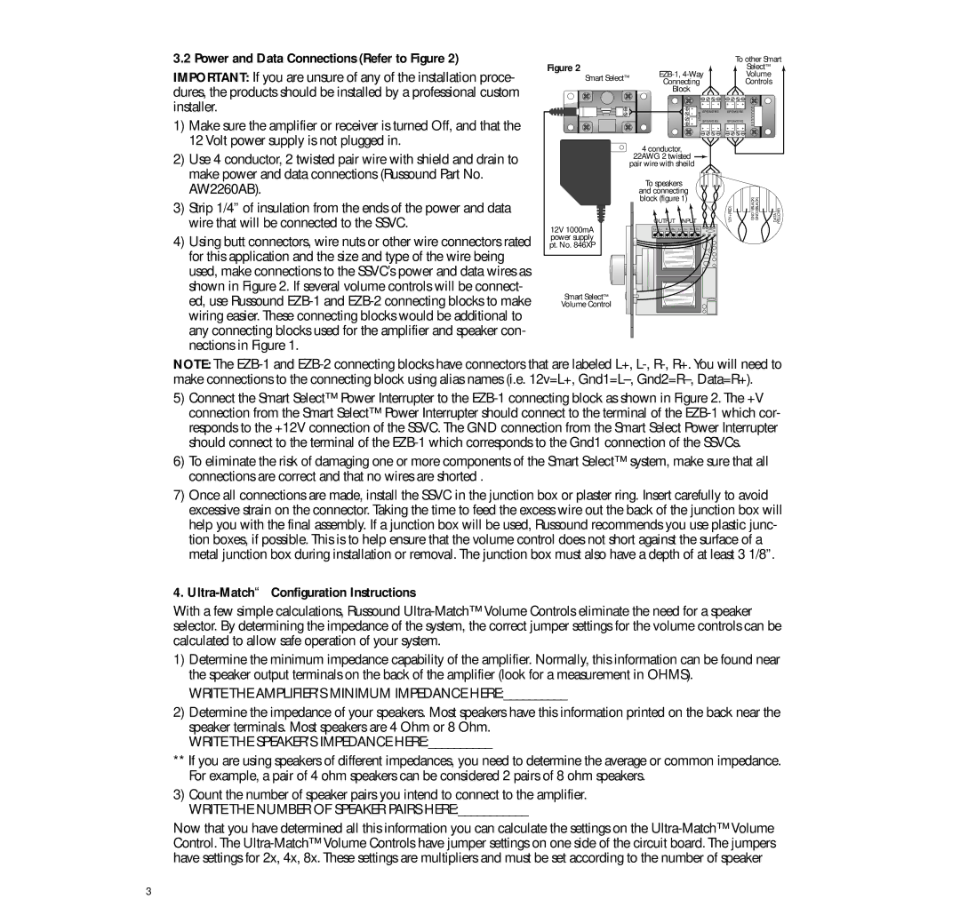
3.2 Power and Data Connections (Refer to Figure 2)
IMPORTANT: If you are unsure of any of the installation proce- dures, the products should be installed by a professional custom installer.
1)Make sure the amplifier or receiver is turned Off, and that the 12 Volt power supply is not plugged in.
2)Use 4 conductor, 2 twisted pair wire with shield and drain to make power and data connections (Russound Part No. AW2260AB).
3)Strip 1/4” of insulation from the ends of the power and data wire that will be connected to the SSVC.
4)Using butt connectors, wire nuts or other wire connectors rated for this application and the size and type of the wire being used, make connections to the SSVC’s power and data wires as shown in Figure 2. If several volume controls will be connect- ed, use Russound
Figure 2 |
|
|
|
|
| To other Smart | ||
| Select™ |
| ||||||
Smart Select™ |
| Volume |
| |||||
| Connecting |
|
| Controls |
| |||
|
|
|
|
| ||||
|
| Block |
|
|
|
|
| |
|
|
|
| INPUT | SPEAKERS | SPEAKERS |
|
|
|
|
|
| SPEAKERS | SPEAKERS |
|
| |
|
|
|
|
|
|
| ||
| 4 conductor, |
|
|
|
|
| ||
| 22AWG 2 twisted |
|
|
|
|
| ||
| pair wire with sheild |
|
|
|
|
| ||
| To speakers |
|
|
|
|
| ||
| and connecting |
|
|
|
|
| ||
| block (figure 1) |
|
|
| GND1(BLACK) GND2(BLACK) |
| ||
| OUTPUT | INPUT |
| 12V+(RED) | DATA (YELLOW) | |||
12V 1000mA | L+ L– | R– R+ | L+ L– R– | R– |
|
|
|
|
|
|
|
|
|
|
|
| |
power supply |
|
|
|
|
|
|
|
|
pt. No. 846XP |
|
|
|
|
|
|
|
|
Smart Select™ |
|
|
|
|
|
|
|
|
Volume Control |
|
|
|
|
|
|
|
|
NOTE: The
5)Connect the Smart Select™ Power Interrupter to the
6)To eliminate the risk of damaging one or more components of the Smart Select™ system, make sure that all connections are correct and that no wires are shorted .
7)Once all connections are made, install the SSVC in the junction box or plaster ring. Insert carefully to avoid excessive strain on the connector. Taking the time to feed the excess wire out the back of the junction box will help you with the final assembly. If a junction box will be used, Russound recommends you use plastic junc- tion boxes, if possible. This is to help ensure that the volume control does not short against the surface of a metal junction box during installation or removal. The junction box must also have a depth of at least 3 1/8”.
4. Ultra-Match™ Configuration Instructions
With a few simple calculations, Russound
1)Determine the minimum impedance capability of the amplifier. Normally, this information can be found near the speaker output terminals on the back of the amplifier (look for a measurement in OHMS).
WRITE THE AMPLIFIER’S MINIMUM IMPEDANCE HERE:__________
2)Determine the impedance of your speakers. Most speakers have this information printed on the back near the speaker terminals. Most speakers are 4 Ohm or 8 Ohm.
WRITE THE SPEAKER’S IMPEDANCE HERE:__________
**If you are using speakers of different impedances, you need to determine the average or common impedance. For example, a pair of 4 ohm speakers can be considered 2 pairs of 8 ohm speakers.
3)Count the number of speaker pairs you intend to connect to the amplifier. WRITE THE NUMBER OF SPEAKER PAIRS HERE:___________
Now that you have determined all this information you can calculate the settings on the
3