INSTALLATION
Location
Locate the VM1 Video Matrix with the host system controller and source equipment to facilitate source and control connections. Locate the VMR1 Receivers near the video displays in the zones, within 300 feet (90 m) of the VM1.
Source Assignments
Because the VM1 tracks the source selections made by the host system, source numbers must match on both systems. Thus, a DVD player connected to source 2 on the multiroom controller also connects to source 2 on the VM1.
Upconverters in the UC and UC2 models provide con- nections only for sources 1, 4, 5, and 8. Be sure to assign your
Upconverter Configuration
Models with upconverters are factory set to convert composite video. Follow the procedure below to set the input switches to
CAUTION
This procedure is for qualified personnel only. To reduce the risk of electric shock, do not perform this procedure unless you are qualified to do so.
1.Turn off the power switch.
2.Unplug the power supply from the VM1 chassis.
3.Remove the 9 cover screws on the rear and sides.
4.Pull the cover up off the chassis, lifting one side first and then the other.
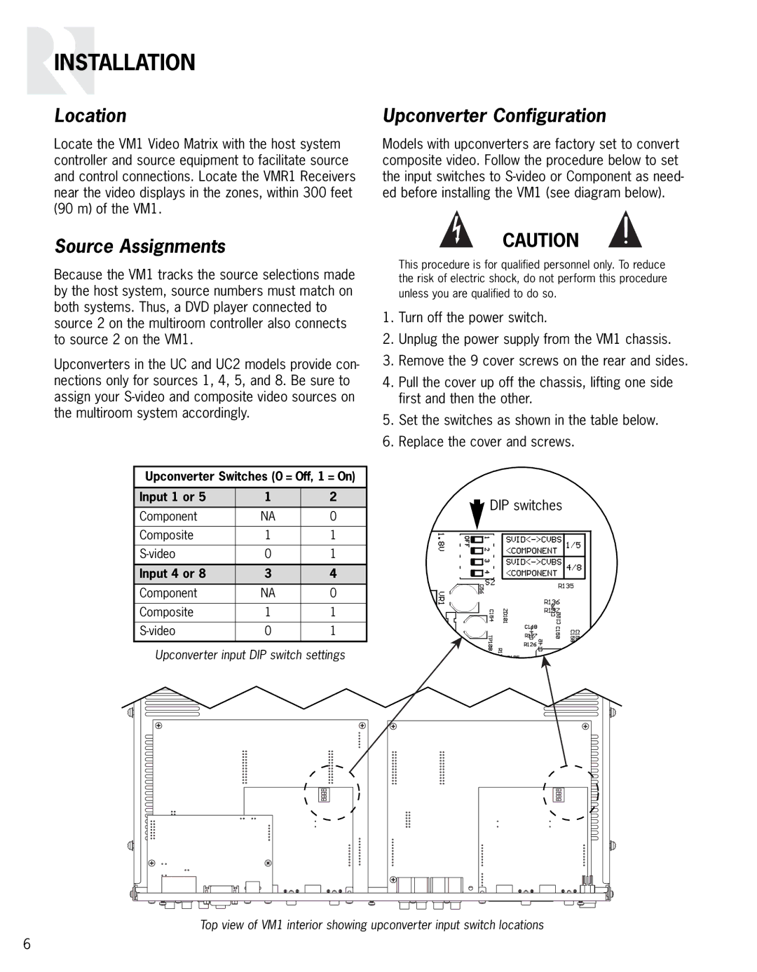
5.Set the switches as shown in the table below.
6.Replace the cover and screws.
Upconverter Switches (0 = Off, 1 = On)
Input 1 or 5 | 1 | 2 |
Component | NA | 0 |
Composite | 1 | 1 |
0 | 1 | |
Input 4 or 8 | 3 | 4 |
Component | NA | 0 |
Composite | 1 | 1 |
0 | 1 |
Upconverter input DIP switch settings
![]() DIP switches
DIP switches
Top view of VM1 interior showing upconverter input switch locations
6