Rack Mounting
To rack mount the VM1, attach the supplied rack ears to the chassis as shown. Leave one rack unit of space open above and below the VM1 to allow prop- er ventilation of the chassis. Do not mount the VM1 above a device that produces high amounts of heat, such as an amplifier.
INSTALLATION
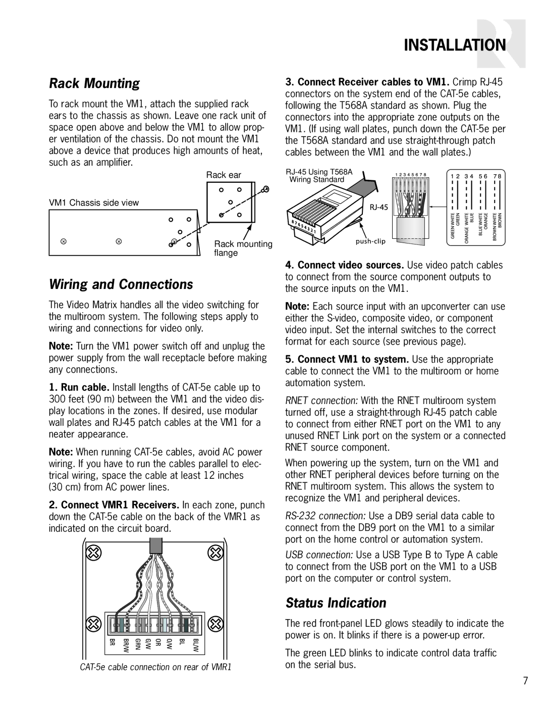
3.Connect Receiver cables to VM1. Crimp
VM1 Chassis side view
+ | + | + |
Rack ear
Rack mounting flange
Wiring Standard
Wiring and Connections
The Video Matrix handles all the video switching for the multiroom system. The following steps apply to wiring and connections for video only.
Note: Turn the VM1 power switch off and unplug the power supply from the wall receptacle before making any connections.
1.Run cable. Install lengths of
300feet (90 m) between the VM1 and the video dis- play locations in the zones. If desired, use modular wall plates and
Note: When running
2.Connect VMR1 Receivers. In each zone, punch down the
4.Connect video sources. Use video patch cables to connect from the source component outputs to the source inputs on the VM1.
Note: Each source input with an upconverter can use either the
5.Connect VM1 to system. Use the appropriate cable to connect the VM1 to the multiroom or home automation system.
RNET connection: With the RNET multiroom system turned off, use a
When powering up the system, turn on the VM1 and other RNET peripheral devices before turning on the RNET multiroom system. This allows the system to recognize the VM1 and peripheral devices.
USB connection: Use a USB Type B to Type A cable to connect from the USB port on the VM1 to a USB port on the computer or control system.
Status Indication
The red
The green LED blinks to indicate control data traffic on the serial bus.
7