OPERATION
ROUGH SURFACE ADAPTOR
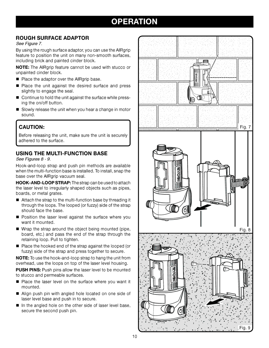
See Figure 7.
By using the rough surface adaptor, you can use the AIRgrip feature to position the unit on many
NOTE: The AIRgrip feature cannot be used with stucco or unpainted cinder block.
Place the adaptor over the AIRgrip base.
Place the unit against the desired surface and press slightly to engage the seal.
Continue to hold the unit against the surface while press- ing the on/off button.
Slowly release the unit when you hear a change in motor sound.
CAUTION:
Before releasing the unit, make sure the unit is securely adhered to the surface.
using the multi-function base
See Figures 8 - 9.
Attach the strap to the
Position the laser level against the surface where you want it mounted.
Wrap the strap around the object being mounted (pipe, board, etc.) and pass the end of the strap through the retaining loop. Pull to tighten.
Place the hooked end of the strap against the looped (or fuzzy) side of the strap and press together to secure.
NOTE: To use the
PUSH PINS: Push pins allow the laser level to be mounted to stucco and permeable surfaces.
Place the laser level on the surface where you want it mounted.
Align push pin with angled hole located on one side of laser level base and push in to secure.
In the angled hole on the other side of laser level base, secure the second push pin.
Fig. 7
Fig. 8
Fig. 9
10