OPERATION
selectING DEPTH OF CUT
Proper depth of cut depends on several factors: the horsepower of the router motor, the type of bit, and the type of wood. A lightweight, low horsepower router is designed for making shallow cuts; a router with higher horsepower is designed for deeper cuts. Small bits, such as veining bits with 1/16 in. cutting diameters, are designed to remove only small amounts of wood. Large bits, such as
Choose a depth of cut that will not place excessive strain on the router motor. If you need extra force or the motor speed slows down considerably, turn off the router and reduce the depth of cut. Then, make the cut in two or more passes.
When routing a groove that is too deep to safely cut in one pass, make the cut in several passes. We recommend that cuts be made at a depth not exceeding 1/8 in. and that several passes be made to reach deeper cuts.
SETting DEPTH OF CUT
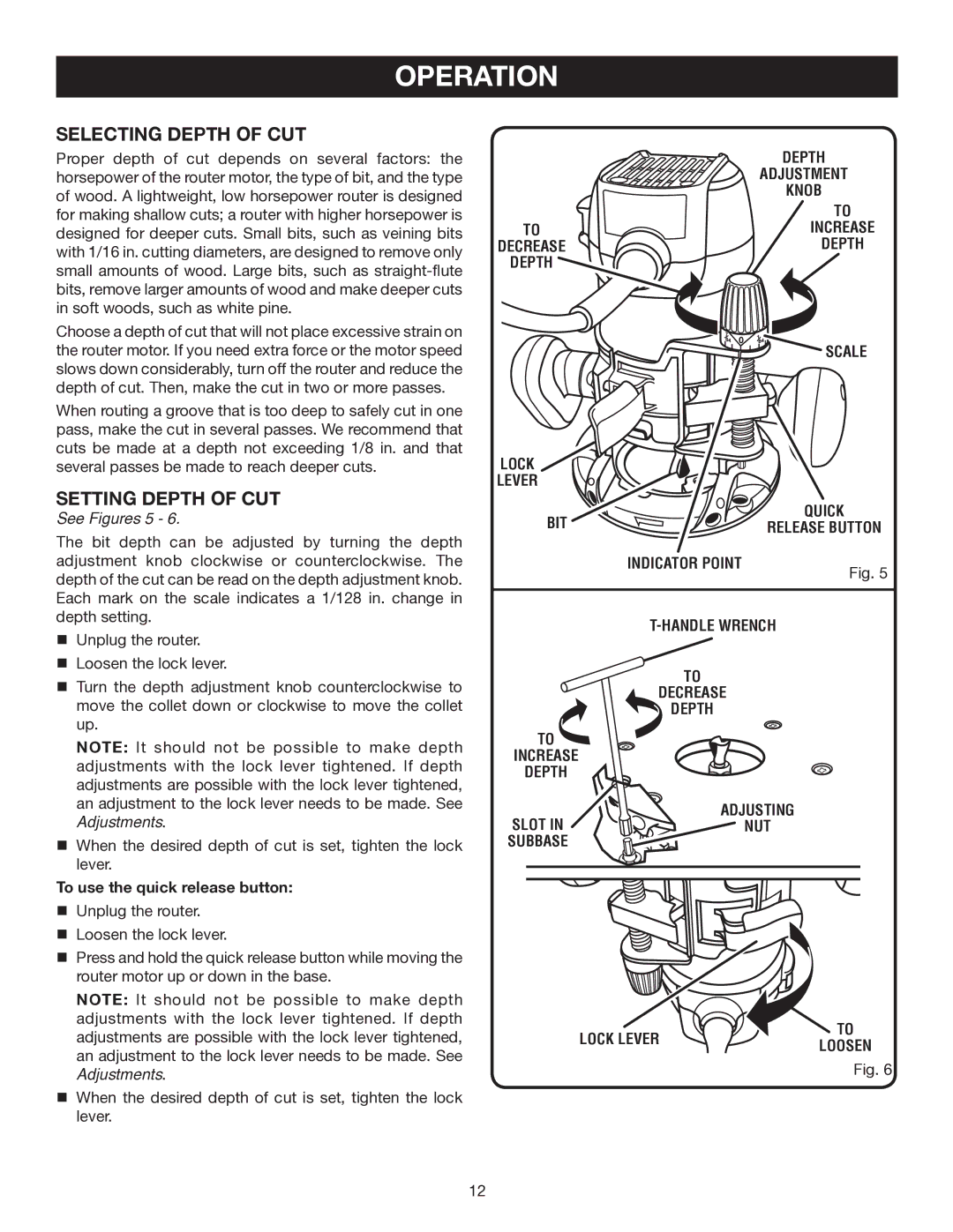
See Figures 5 - 6.
The bit depth can be adjusted by turning the depth adjustment knob clockwise or counterclockwise. The depth of the cut can be read on the depth adjustment knob. Each mark on the scale indicates a 1/128 in. change in depth setting.
nUnplug the router.
nLoosen the lock lever.
nTurn the depth adjustment knob counterclockwise to move the collet down or clockwise to move the collet up.
Note: It should not be possible to make depth adjustments with the lock lever tightened. If depth adjustments are possible with the lock lever tightened, an adjustment to the lock lever needs to be made. See Adjustments.
nWhen the desired depth of cut is set, tighten the lock lever.
To use the quick release button:
nUnplug the router.
nLoosen the lock lever.
nPress and hold the quick release button while moving the router motor up or down in the base.
Note: It should not be possible to make depth adjustments with the lock lever tightened. If depth adjustments are possible with the lock lever tightened, an adjustment to the lock lever needs to be made. See Adjustments.
nWhen the desired depth of cut is set, tighten the lock lever.
| DEPTH |
| ADJUSTMENT |
| KNOB |
| TO |
TO | INCREASE |
DECREASE | DEPTH |
DEPTH |
|
| SCALE |
LOCK |
|
|
LEVER |
|
|
BIT |
| QUICK |
RELEASE BUTTON | ||
| INDICATOR POINT | Fig. 5 |
|
| |
|
| |
| TO |
|
| DECREASE |
|
| DEPTH |
|
TO |
|
|
INCREASE |
|
|
DEPTH |
|
|
SLOT IN | ADJUSTING |
|
NUT |
| |
SUBBASE |
|
|
LOCK LEVER | TO | |
LOOSEN | ||
|
Fig. 6
12