CUTTER BAR MOWER
WARNING
•When you transport your machine, and when you finish work, always fit the knife guard over the cut- ter bar.
•Keep your hands and feet clear of the cutter bar when in motion.
•Do not operate the
•Stop the engine before cleaning the attachment.
•Stop the engine before adjusting the knife wear plate.
GENERAL
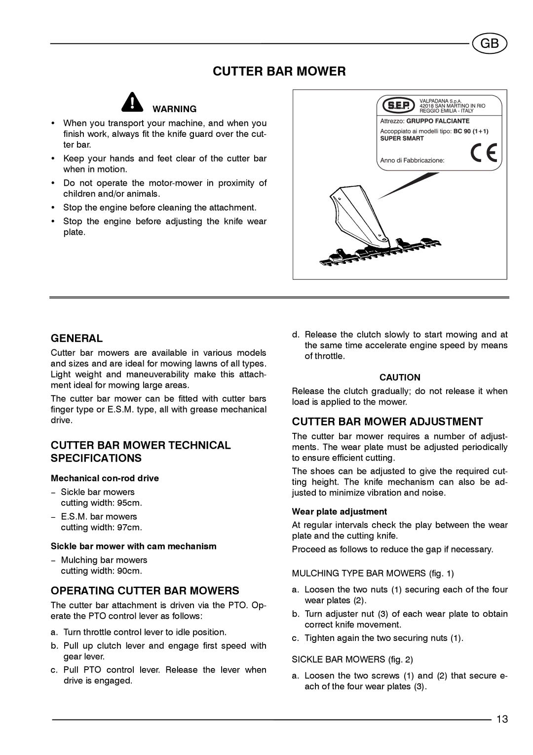
Cutter bar mowers are available in various models and sizes and are ideal for mowing lawns of all types. Light weight and maneuverability make this attach- ment ideal for mowing large areas.
The cutter bar mower can be fitted with cutter bars finger type or E.S.M. type, all with grease mechanical drive.
CUTTER BAR MOWER TECHNICAL SPECIFICATIONS
Mechanical
−Sickle bar mowers cutting width: 95cm.
−E.S.M. bar mowers cutting width: 97cm.
Sickle bar mower with cam mechanism
−Mulching bar mowers cutting width: 90cm.
OPERATING CUTTER BAR MOWERS
The cutter bar attachment is driven via the PTO. Op- erate the PTO control lever as follows:
a.Turn throttle control lever to idle position.
b.Pull up clutch lever and engage first speed with gear lever.
c.Pull PTO control lever. Release the lever when drive is engaged.
d.Release the clutch slowly to start mowing and at the same time accelerate engine speed by means of throttle.
CAUTION
Release the clutch gradually; do not release it when load is applied to the mower.
CUTTER BAR MOWER ADJUSTMENT
The cutter bar mower requires a number of adjust- ments. The wear plate must be adjusted periodically to ensure efficient cutting.
The shoes can be adjusted to give the required cut- ting height. The knife mechanism can also be ad- justed to minimize vibration and noise.
Wear plate adjustment
At regular intervals check the play between the wear plate and the cutting knife.
Proceed as follows to reduce the gap if necessary.
MULCHING TYPE BAR MOWERS (fig. 1)
a.Loosen the two nuts (1) securing each of the four wear plates (2).
b.Turn adjuster nut (3) of each wear plate to obtain correct knife movement.
c.Tighten again the two securing nuts (1).
SICKLE BAR MOWERS (fig. 2)
a.Loosen the two screws (1) and (2) that secure e- ach of the four wear plates (3).
13
