PL2404 specifications
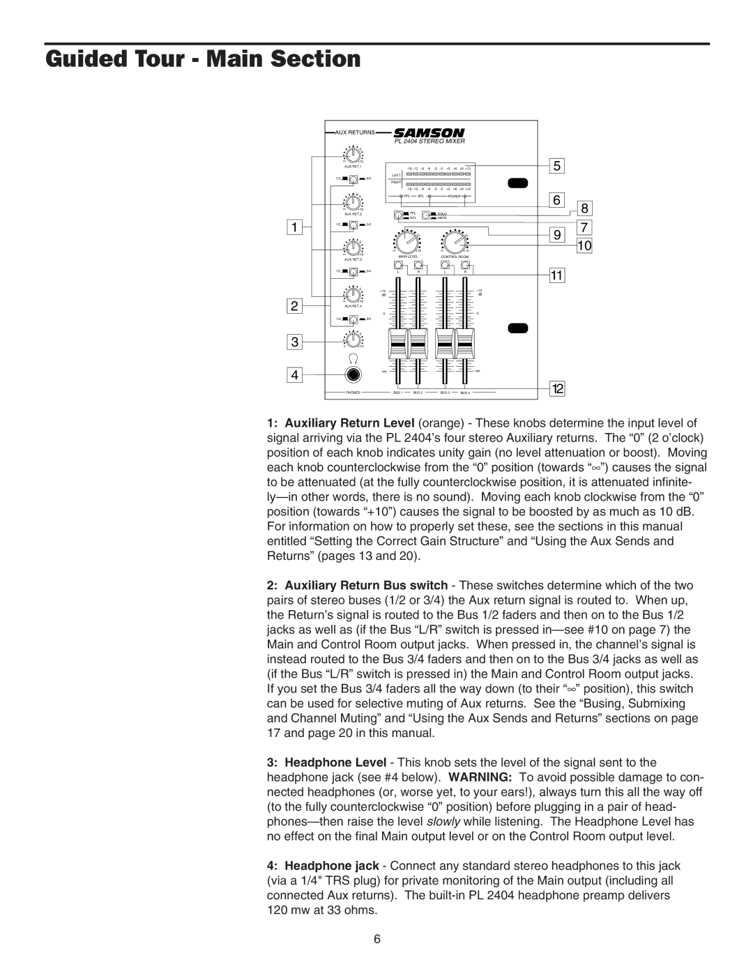
The Samson PL2404 is a sophisticated audio mixer that stands out in the realm of live sound and studio applications. It is designed for professionals seeking versatility, quality, and robust performance in a compact package.One of the main features of the PL2404 is its 24-channel configuration, which allows users to handle a variety of audio sources simultaneously. Each channel is equipped with a 3-band EQ, providing precise control over high, mid, and low frequencies. This EQ section helps audio engineers shape the sound of individual channels to achieve optimal mix clarity.
The mixer also includes 4 subgroups, which enable the grouping of channels for simplified control over multiple inputs. This is particularly useful for live performances or large events, as it streamlines the mixing process and allows for quick adjustments. Each subgroup can be routed to the main mix or through auxiliary outputs, offering greater flexibility.
In terms of connectivity, the PL2404 features a range of options, including XLR inputs for microphones, 1/4" TRS inputs for line-level devices, and various send/return options for external effects processors. This diverse range of inputs and outputs makes it easy to integrate the mixer into a variety of audio setups.
The PL2404 also incorporates advanced technologies designed to enhance audio quality. Its low-noise preamps ensure that every sound source is captured with clarity, while the mixer’s overall design minimizes signal interference and crosstalk. This ensures that whether you’re recording in a studio or mixing live, the integrity of the sound is maintained.
Additional characteristics of the PL2404 include a built-in talkback function, which allows the engineer to communicate with performers or other crew members without disrupting the mix. The intuitive layout of controls ensures quick access to essential functions for both novice and experienced users.
The PL2404’s rugged construction makes it suitable for touring, as it can withstand the rigors of constant transportation. Its lightweight yet durable chassis is designed to endure the wear and tear of frequent use, ensuring reliability in demanding environments.
In summary, the Samson PL2404 is a versatile audio mixer that combines professional features and advanced technology, making it an excellent choice for both live and studio applications. Its quality, flexibility, and durability make it a trusted tool for audio professionals.

