Guided Tour -
Wireless EarAmp® Transmitter Front Panel
1 
 2a
2a
 2b
2b
SAMSON PHONES
POWER | RT80 UHF SYNTHESIZED |
3 | 4 |
PHONES LEVEL |
| INPUT LEVEL | EarAmp® | ||||||
|
|
|
|
|
|
|
| S T E R E O T R A N S M I T T E R |
|
0 | 2 |
| 0 | 2 |
|
|
| ||
| 4 |
|
|
| 4 |
|
| ||
| 6 |
|
|
| 6 |
|
| ||
| 8 |
|
|
| 8 |
|
| ||
| 10 |
|
| 10 |
|
|
| ||
| 5 | 6 | 7 | 8 | 9 | 10 |
LEFT | +6 | RIGHT |
|
|
|
|
|
| CH. |
| UP |
| PROGRAM |
| 0 |
|
|
| ||
|
|
|
|
|
| |
| GROUP |
|
|
|
| |
|
|
| DOWN |
|
| |
|
|
|
|
|
| |
| FREQ |
|
|
|
|
11
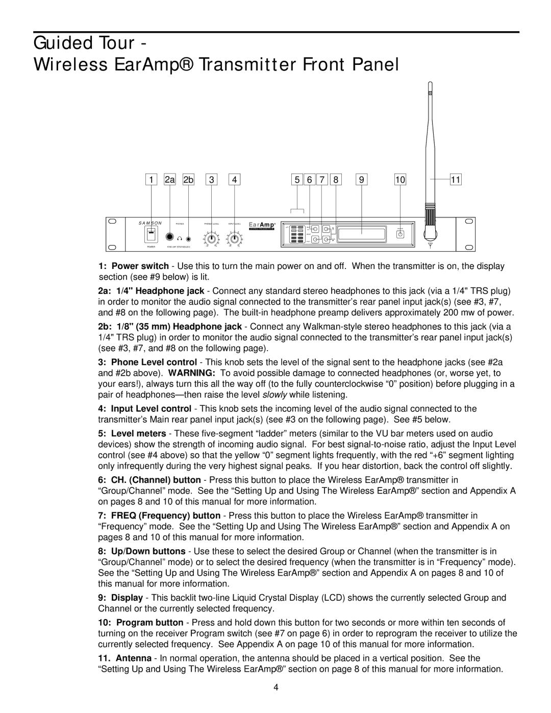
1:Power switch - Use this to turn the main power on and off. When the transmitter is on, the display section (see #9 below) is lit.
2a: 1/4" Headphone jack - Connect any standard stereo headphones to this jack (via a 1/4" TRS plug) in order to monitor the audio signal connected to the transmitter’s rear panel input jack(s) (see #3, #7, and #8 on the following page). The
2b: 1/8" (35 mm) Headphone jack - Connect any
3:Phone Level control - This knob sets the level of the signal sent to the headphone jacks (see #2a and #2b above). WARNING: To avoid possible damage to connected headphones (or, worse yet, to your ears!), always turn this all the way off (to the fully counterclockwise “0” position) before plugging in a pair of
4:Input Level control - This knob sets the incoming level of the audio signal connected to the transmitter’s Main rear panel input jack(s) (see #3 on the following page). See #5 below.
5:Level meters - These
6:CH. (Channel) button - Press this button to place the Wireless EarAmp® transmitter in “Group/Channel” mode. See the “Setting Up and Using The Wireless EarAmp®” section and Appendix A on pages 8 and 10 of this manual for more information.
7:FREQ (Frequency) button - Press this button to place the Wireless EarAmp® transmitter in “Frequency” mode. See the “Setting Up and Using The Wireless EarAmp®” section and Appendix A on pages 8 and 10 of this manual for more information.
8:Up/Down buttons - Use these to select the desired Group or Channel (when the transmitter is in “Group/Channel” mode) or to select the desired frequency (when the transmitter is in “Frequency” mode). See the “Setting Up and Using The Wireless EarAmp®” section and Appendix A on pages 8 and 10 of this manual for more information.
9:Display - This backlit
10:Program button - Press and hold down this button for two seconds or more within ten seconds of turning on the receiver Program switch (see #7 on page 6) in order to reprogram the receiver to utilize the currently selected frequency. See Appendix A on page 10 of this manual for more information.
11.Antenna - In normal operation, the antenna should be placed in a vertical position. See the “Setting Up and Using The Wireless EarAmp®” section on page 8 of this manual for more information.
4