Installation
Accessories in the outdoor unit package
Rubber leg (4)
![]() NOTE
NOTE
•A flare nut is attached to the end of each pipe of an evaporator or a service port. Use flare nuts when connecting the pipes.
•Wire assembly cables are optional. If they are not supplied, use standard cables.
•The drain plug and the rubber legs are included only when the air conditioner is supplied without assembly pipes.
•If these accessories are supplied, they are in the accessory package or outdoor unit package.
Tools
General tools
•Vacuum pump
(Backward flowing prevention)
•Manifold gauge
•Stud finder
•Torque wrench
•Pipe cutter
•Reamer
•Pipe bender
•Spirit level
•Screwdriver
•Spanner
•Drill
•
•Measuring tape
Tools for test operation
•Thermometer
•Resistance meter
•Electroscope
Step 1.4 Drilling a hole through the wall
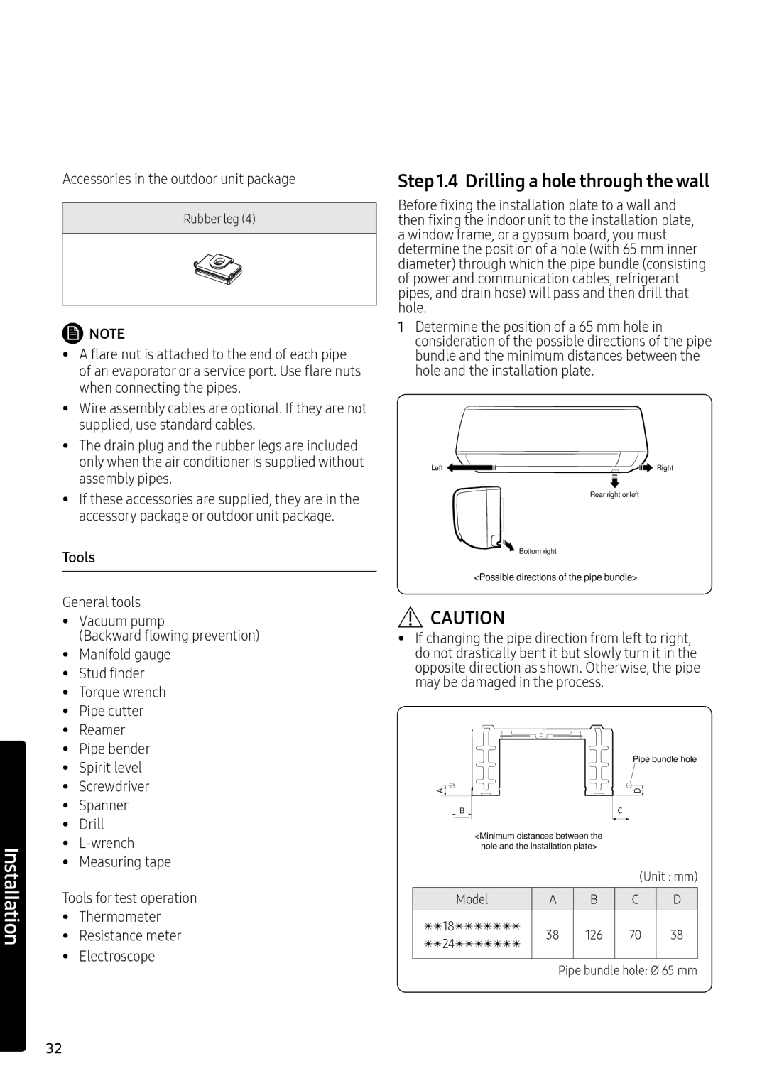
Before fixing the installation plate to a wall and then fixing the indoor unit to the installation plate, a window frame, or a gypsum board, you must determine the position of a hole (with 65 mm inner diameter) through which the pipe bundle (consisting of power and communication cables, refrigerant pipes, and drain hose) will pass and then drill that hole.
1Determine the position of a 65 mm hole in consideration of the possible directions of the pipe bundle and the minimum distances between the hole and the installation plate.
Left ![]()
![]()
![]()
![]()
![]() Right
Right
Rear right or left
![]() Bottom right
Bottom right
<Possible directions of the pipe bundle>
![]() CAUTION
CAUTION
•If changing the pipe direction from left to right, do not drastically bent it but slowly turn it in the opposite direction as shown. Otherwise, the pipe may be damaged in the process.
Pipe bundle hole
<Minimum distances between the hole and the installation plate>
(Unit : mm)
Model | A | B | C | D | |
|
|
|
|
| |
✴✴18✴✴T✴✴✴✴ | 38 | 126 | 70 | 38 | |
✴✴24✴✴T✴✴✴✴ | |||||
|
|
|
| ||
|
|
|
|
| |
| Pipe bundle hole: Ø 65 mm | ||||
32English
