| Printer Installation Guide |
THERMAL PRINTER | |
|
|
◈Information
This Installation Guide includes a brief outline of information necessary for product installation. For more detailed installation information, please refer to the user manual in the enclosed CD. The contents of the CD include the following.
1.Manual: User Manual, Code Chart, Control Commands
2.Drivers: Windows Drivers, OPOS Drivers
3.Utilities: a Logo download tool and a virtual memory switch control tool
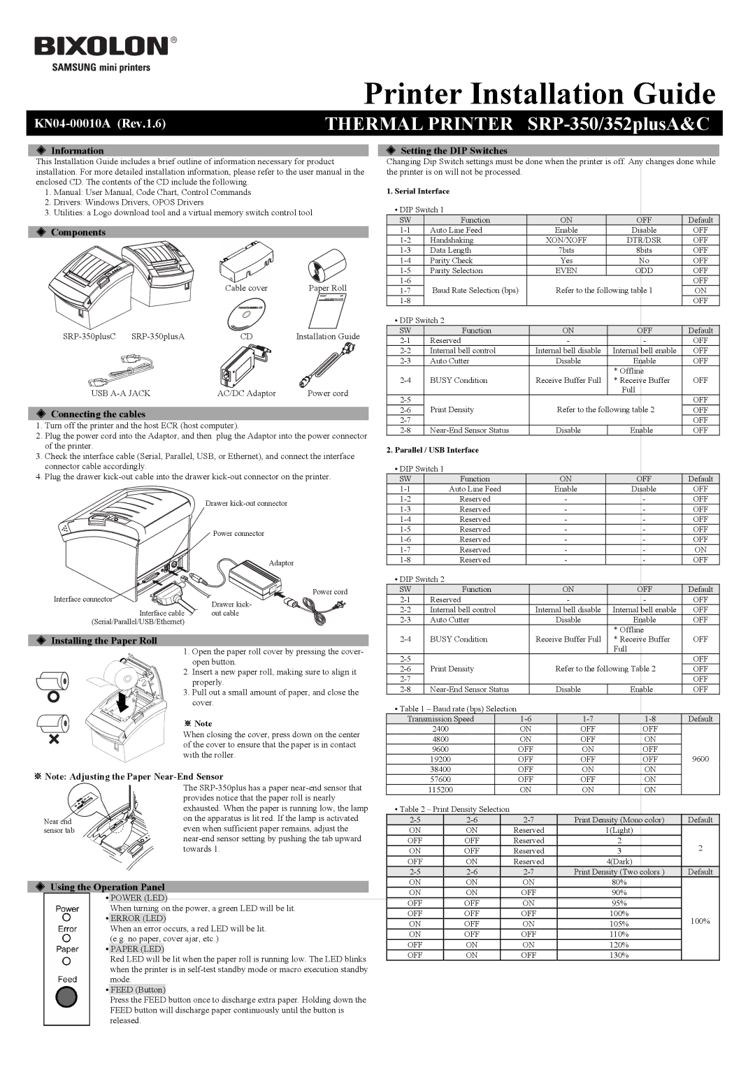
◈Components
| Cable cover | Paper Roll |
| Procuct Installation CD |
|
CD | Installation Guide | |
USB | AC/DC Adaptor | Power cord |
◈Connecting the cables
1.Turn off the printer and the host ECR (host computer).
2.Plug the power cord into the Adaptor, and then plug the Adaptor into the power connector of the printer.
3.Check the interface cable (Serial, Parallel, USB, or Ethernet), and connect the interface connector cable accordingly.
4.Plug the drawer
| Drawer | |
| Power connector | |
| Adaptor | |
Interface connector | Power cord | |
Drawer kick- | ||
Interface cable | ||
out cable | ||
(Serial/Parallel/USB/Ethernet) |
|
◈Installing the Paper Roll
1. Open the paper roll cover by pressing the cover- open button.
2. Insert a new paper roll, making sure to align it properly.
3. Pull out a small amount of paper, and close the cover.
※ Note
When closing the cover, press down on the center of the cover to ensure that the paper is in contact with the roller.
※Note: Adjusting the Paper Near-End Sensor
| The |
| provides notice that the paper roll is nearly |
| exhausted. When the paper is running low, the lamp |
Near end | on the apparatus is lit red. If the lamp is activated |
sensor tab | even when sufficient paper remains, adjust the |
◈Using the Operation Panel
•POWER (LED)
When turning on the power, a green LED will be lit.
•ERROR (LED)
When an error occurs, a red LED will be lit. (e.g. no paper, cover ajar, etc.)
•PAPER (LED)
Red LED will be lit when the paper roll is running low. The LED blinks when the printer is in
•FEED (Button)
Press the FEED button once to discharge extra paper. Holding down the FEED button will discharge paper continuously until the button is released.
◈Setting the DIP Switches
Changing Dip Switch settings must be done when the printer is off. Any changes done while the printer is on will not be processed.
1.Serial Interface
• DIP Switch 1
SW | Function | ON | OFF | Default |
Auto Line Feed | Enable | Disable | OFF | |
Handshaking | XON/XOFF | DTR/DSR | OFF | |
Data Length | 7bits | 8bits | OFF | |
Parity Check | Yes | No | OFF | |
Parity Selection | EVEN | ODD | OFF | |
Baud Rate Selection (bps) | Refer to the following table 1 | OFF | ||
ON | ||||
|
|
| OFF | |
• DIP Switch 2 |
|
|
| |
SW | Function | ON | OFF | Default |
Reserved | - | - | OFF | |
Internal bell control | Internal bell disable | Internal bell enable | OFF | |
Auto Cutter | Disable | Enable | OFF | |
BUSY Condition | Receive Buffer Full | * Offline | OFF | |
* Receive Buffer | ||||
|
|
| Full |
|
Print Density | Refer to the following table 2 | OFF | ||
OFF | ||||
|
|
| OFF | |
Disable | Enable | OFF | ||
2.Parallel / USB Interface
• DIP Switch 1
| SW |
|
| Function |
|
|
| ON |
|
| OFF | Default | ||||
| Auto Line Feed |
|
| Enable |
|
| Disable | OFF | ||||||||
|
| Reserved |
|
| - | - |
| OFF | ||||||||
|
| Reserved |
|
| - | - |
| OFF | ||||||||
|
| Reserved |
|
| - | - |
| OFF | ||||||||
|
| Reserved |
|
| - | - |
| OFF | ||||||||
|
| Reserved |
|
| - | - |
| OFF | ||||||||
|
| Reserved |
|
| - | - |
| ON | ||||||||
|
| Reserved |
|
| - | - |
| OFF | ||||||||
| • DIP Switch 2 |
|
|
|
|
|
|
|
|
|
| |||||
| SW |
|
| Function |
|
|
| ON |
|
| OFF | Default | ||||
Reserved |
|
| - | - |
| OFF | ||||||||||
Internal bell control |
| Internal bell disable | Internal bell enable | OFF | ||||||||||||
Auto Cutter |
|
| Disable |
|
| Enable | OFF | |||||||||
|
|
|
|
|
|
|
|
|
|
| * Offline |
|
| |||
BUSY Condition |
| Receive Buffer Full | * Receive Buffer | OFF | ||||||||||||
|
|
|
|
|
|
|
|
|
|
| Full |
|
| |||
Print Density |
|
| Refer to the following Table 2 | OFF | ||||||||||||
|
| OFF | ||||||||||||||
|
|
|
|
|
|
|
|
|
|
|
|
| OFF | |||
|
| Disable |
|
| Enable | OFF | ||||||||||
| • Table 1 – Baud rate (bps) Selection |
|
|
|
|
|
|
|
| |||||||
| Transmission Speed |
|
|
|
|
|
| Default | ||||||||
|
| 2400 |
|
|
| ON |
| OFF |
|
| OFF |
|
| |||
|
| 4800 |
|
|
| ON |
| OFF |
|
| ON |
|
| |||
|
| 9600 |
|
|
| OFF |
| ON |
|
| OFF | 9600 |
| |||
|
| 19200 |
|
| OFF |
| OFF |
|
| OFF |
| |||||
|
| 38400 |
|
| OFF |
| ON |
|
| ON |
|
| ||||
|
| 57600 |
|
| OFF |
| OFF |
|
| ON |
|
| ||||
|
| 115200 |
|
| ON |
| ON |
|
| ON |
|
| ||||
| • Table 2 – Print Density Selection |
|
|
|
|
|
|
|
|
|
| |||||
|
|
|
|
|
| Print Density (Mono color) |
| Default |
| |||||||
| ON |
|
| ON |
| Reserved |
|
| 1(Light) |
|
| |||||
| OFF |
|
| OFF |
| Reserved |
|
| 2 |
|
| 2 |
| |||
| ON |
|
| OFF |
| Reserved |
|
| 3 |
|
|
| ||||
|
|
|
|
|
|
|
|
|
| |||||||
| OFF |
|
| ON |
| Reserved |
|
| 4(Dark) |
|
| |||||
|
|
|
|
|
| Print Density (Two colors ) |
| Default |
| |||||||
| ON |
|
| ON |
| ON |
|
| 80% |
|
|
| ||||
| ON |
|
| ON |
| OFF |
|
| 90% |
|
|
| ||||
| OFF |
|
| OFF |
| ON |
|
| 95% |
|
|
| ||||
| OFF |
|
| OFF |
| OFF |
|
| 100% |
| 100% |
| ||||
| ON |
|
| OFF |
| ON |
|
| 105% |
|
| |||||
|
|
|
|
|
|
|
|
| ||||||||
| ON |
|
| OFF |
| OFF |
|
| 110% |
|
|
| ||||
| OFF |
|
| ON |
| ON |
|
| 120% |
|
|
| ||||
| OFF |
|
| ON |
| OFF |
|
| 130% |
|
|
| ||||