Case 1. TV

Case 2. TV+Signage

Step2 - Type A


Components /

Composants /

Componentes

Preparations before installation

A


Quick Setup Guide

Guide d'installation rapide

Guía de configuración rápida

SMART Signage TV

RM40D RM48D

You can use the product as a TV, and as signage (advertisement media) using the Content Creator program on your computer.

-The warranty will be void in the event of a breakdown due to exceeding the maximum recommended hours of use per day of 16 hours.

Vous pouvez utiliser le produit en tant que téléviseur et pour la signalisation (support publicitaire) à l’aide du programme Créateur de contenu de votre ordinateur.

-La garantie s'annule en cas de panne due à une durée d'utilisation supérieure à celle recommandée par jour (16 heures).

Puede usar el producto como televisor y como Signage (multimedia publicitario) mediante el programa Creador de contenido de su ordenador.

-La garantía quedará anulada en caso de que se produzca una avería causada por sobrepasar el número máximo de horas de uso diario (16 horas).

The terms HDMI and HDMI High-Definition Multimedia Interface, and the

HDMI Logo are trademarks or registered trademarks of HDMI Licensing LLC in

To use it as a TV only, follow Step1 through Step4.

Pour l’utiliser en tant que téléviseur uniquement, suivez la procédure Step1 à Step4.

Para usarlo solo como televisor, siga los pasos Step1 al Step4.

Step1 ~ 4

To use it as a TV+signage, follow Step1 through Step6.

Pour l’utiliser en tant que téléviseur et pour la signalisation, suivez la procédure Step1 à Step6.

Para usarlo como televisor+signage, siga los pasos Step1 al Step6.

Step1 ~ 6

1


VESA STANDARD

B

C


X 8

Préparation avant installation /

Preparativos antes de la instalación


1-1

1-2

1-3


The product can be installed in either landscape or portrait orientation. Select an orientation.


Place A (Drill guide sheet) on the back of the product to con￿rm the locations of VESA holes.


* If installing the product in portrait orientation, TV broadcasts and video playback may be limited.


* To install the product in portrait orientation, lay it down vertically to test the requirements.


You can create content using the Content Creator program.


Placez A (Feuille de guidage pour le perçage) au dos du produit pour véri￿er l'emplacement des


Le produit peut être installé en utilisant l’orientation portrait ou paysage. Sélectionnez une orientation.


ori￿ces VESA.


* Si vous installez le produit en orientation Portrait, les diffusions TV et la lecture vidéo peuvent


* Si vous souhaitez installer le produit en utilisant l’orientation portrait, posez-le verticalement

Place the product on a soft cloth to protect the panel.


être limitées. Vous pouvez créer des contenus à l'aide du programme Créateur de contenu.


de manière à tester les conditions requises.


El producto puede instalarse tanto en orientación horizontal como vertical. Seleccione una orientación.


Coloque A (Hoja de guía para taladrar) en la parte posterior del producto, para con￿rmar la

Placez le produit sur un tissu doux pour protéger le panneau.


* Si instala el producto con orientación vertical, es posible que la reproducción de vídeos y


ubicación de los ori￿cios VESA.

Coloque el producto sobre un paño suave para proteger el panel.


programas de televisión sufra alguna limitación. Puede crear contenido mediante el programa


* Para instalar el producto en orientación vertical, colóquelo verticalmente para comprobar


Creador de contenido.


los requisitos.

the United States and other countries.

BN68-06719B-04


1-4

1-5

B


1-6

B

Step1 Unpack Déballage / Desembalar

The following images are for reference only. Real-life situations may differ from what is shown in the images.

Components may vary depending on the country and model. Store the box in a dry area so that it can be used when moving the product in the future. * Make sure no component is missing in the package. Contact the vendor where you purchased the product if any components are missing.

* The Mini Wall-mount Kit may not be supported, depending on the model.

Step2 Install


Installation /


Instalar


Type B


Type A


A

A

C

Les images suivantes servent uniquement de référence. Les situations réelles peuvent différer de celles illustrées ci-dessous.

Les composants peuvent varier selon le pays et le modèle. Rangez la boîte dans un endroit sec, de sorte que vous puissiez la réutiliser pour déplacer le produit ultérieurement.

*Vérifiez que tous les composants sont bien inclus. S'il manque le moindre composant, contactez le revendeur auprès duquel vous avez acheté le produit.

*Il est possible que le mini kit de montage mural ne soit pas compatible, en fonction du modèle.

Las imágenes siguientes tienen fines de referencia únicamente. Las situaciones reales pueden diferir de lo que se muestra en estas imágenes.

Los componentes pueden variar según el país y el modelo. Guarde la caja en una zona seca para volverla a utilizar si necesita mover el producto en el futuro.

Wall Mount Type Type de montage mural

Tipo de montaje mural

Stand Type Type de support

Tipo de soporte

Remove the paper tape at the center of A (Drill guide sheet).


Attach B (Leveler) to the appropriate spot at the center of A (Drill guide sheet).


Retirez la bande de papier au centre de la feuille de guidage pour le perçage (A).


Placez le dispositif de mise à niveau (B) à l’emplacement adapté, au centre de la


Quite la tira de papel ubicada en el centro de A (Hoja de guía para taladrar).


feuille de guidage pour le perçage (A).


Acople B (Nivel) en el lugar apropiado en el centro de A (Hoja de guía para taladrar).


Fix A (Drill guide sheet) to the wall using C (Sticker). Make sure that B (Leveler) is level.

Fixez le guide pour le perçage (A) au mur à l’aide de l’autocollant (C). Veillez à ce que le dispositif de mise à niveau (B) soit de niveau.

Fije A (Guía para taladrar) a la pared mediante C (Pegatina). Asegúrese de que B (Nivel) está efectivamente a nivel.

*Asegúrese de que el paquete incluye todos los componentes necesarios. Póngase en contacto con el distribuidor donde adquirió el producto si falta alguno de los componentes.

*Dependiendo del modelo es posible que no se admita el mini equipo de montaje mural.

Included components Composants inclus

Included components Composants inclus

Installing the wall-mount kit

Components / Composants / Componentes

D

E

F

H

X 4


G


1 2 3 4

5 6 7

8 9 0

1

Quick setup guide

1

Guide d'installation rapide

1

Guía de configuración rápida

2

Warranty card

2

Carte de garantie

2

Tarjeta de garantía


(Not available in some locations)


(Non disponible dans certains pays)


(No disponible en todos los lugares.)

3

Regulatory guide

3

Guide réglementaire

3

Guía de regulaciones

4

User manual /

4

Manuel utilisateur / Programme

4

Manual del usuario /


MagicInfo Express Content


MagicInfo Express Créateur de


MagicInfo Express Creador de


Creator (USB or DVD)


contenu (USB ou DVD)


contenido (USB o DVD)

5

Mini Wall-mount Kit

5

Mini-kit de montage mural

5

Juego de mini-montaje mural


(optional)


(en option)


(opcional)

6

Stand base

6

Base du support

6

Base del soporte

7

Stand neck

7

Col du support

7

Conector del soporte

8

Remote Control

8

Télécommande

8

Mando a distancia

9

Batteries

9

Batteries

9

Pilas


(Not available in some locations)


(Non disponible dans certains pays)


(No disponible en todos los lugares.)

0

Power cord

0

Cordon d'alimentation

0

Cable de alimentación

Componentes incluidos

To install the product using the wall-mount

kit, refer to "Wall Mount Installation".

Pour installer le produit à l’aide du kit de montage mural, reportez-vous à la section

«Installation du mini-support mural ».

Para instalar el producto usando el juego de montaje mural, consulte "Instalación de montaje mural".

Componentes incluidos

To install the product using the stand, refer to "Stand Installation" on the next page.

Pour installer le produit à l’aide du support, reportez-vous à la section « Installation du support », à la page suivante.

Para instalar el producto usando el soporte, consulte "Instalación del soporte" en la página siguiente.

2


Installation du kit de montage mural /


2-1 1

5mm (0.2")

2

65 mm (2.6")


2mm (3/32")


9mm (11/32")


H

Instalación del juego de montaje mural

X 2

X 2

X 2


I

X 4

2-2

2-3


D

H


E


I D


Fasten D (Bracket Distance) to H (Plastic Anchor) on the wall, using I (Screw).


Insert the tab of D (Bracket Distance) into the hole of E (Cover Distance).


Fixez le support d’écartement (D) sur le dispositif d’ancrage en plastique (H) au mur à l’aide


Insérez la languette du support d’écartement (D) dans le trou du cache


de la vis (I).


d’écartement (E).


Apriete D (Distancia de soporte) a H (Taco de plástico) en la pared, sirviéndose de I (Tornillo).


Inserte la pestaña de D (Distancia de soporte) en el orificio de E (Distancia


2-4

2-5


de cubierta).


Step2 - Type A

Wall Mount Installation / Installation du mini-support mural / Instalación de montaje mural

G

Precautions when installing the wall-mount kit

Précautions lors de l’installation du kit de montage mural / Precauciones para la instalación del juego de montaje mural

Check the type of the wall before installing.

Identifiez le type de mur avant de procéder à l’installation. / Compruebe el tipo de pared en la que va a instalar el producto.

Make sure the wall where the provided mini wall mount kit will be installed is flat, smooth and perfectly vertical. Dry Wall, Gypsum-board, SheetRock: Please use a qualified installer to install the Wall Mount Bracket.

Veillez à ce que le mur sur lequel le mini-kit de montage mural doit être installé soit plat, lisse et parfaitement vertical. Cloison sèche ou plaque de plâtre : Veuillez faire appel à un installateur qualifié pour installer le support mural.

Asegúrese de que la pared en la que va a instalar el mini-montaje mural está plana, lisa y perfectamente vertical. Pladur, yeso laminado, cartón yeso: Contrate a un instalador cualificado para el soporte de montaje mural.

Standard Installation Requirements by Wall Type

Conditions d’installation standard en fonction du type de mur / Requisitos de instalación estándar según el tipo de pared

*MDF = Medium Density Fiberboard

*PW = Plywood

Min. 50mm


Min.


Min.


25mm


25mm


Min. 30mm


Min. 30mm


Min.


MDF, PW, etc.

50mm

MDF, PW

MDF, PW


Concrete


Mixed Concrete

With reinforcement


Art Wall

(Exc. drywall

Art Wall


Wall (Exc. drywall


thickness)


thickness)

Min. 10mm


Min. 10mm


Min. 10mm


MDF, PW


MDF, PW


MDF, PW


Cannot be mounted on unreinforced wall or drywall surfaces.

Ne peut être installé sur des murs ou des surfaces à cloison sèche non renforcés. / No puede montarse sobre paredes sin armar ni sobre superficies de yeso o pladur.

MDF, PW,


Concrete


Art Wall

Without

Drywall

0~24mm


reinforcement


Cannot install on drywall


Installing on a drywall with stud reinforcements

Installation sur une cloison sèche avec goujons de renfort / Instalación en pared de yeso o pladur con montantes de refuerzo

65mm(2.5")

Wall

Mur

Pared

<Installation is complete> <Installation terminée>

<Se ha completado la instalación>

c Checking the Components

Véri￿cation des composants / Comprobación de los componentes

Contact the dealer where you purchased the

Contactez le revendeur qui vous a vendu

Si falta alguno de los componentes póngase

product if any components are missing.

le produit en cas d'absence de certains

en contacto con el distribuidor donde haya

The appearance of the components may

composants.

adquirido el producto.

differ from the images shown.

Les composants peuvent être différents de

El aspecto de los componentes puede ser


ceux illustrés ici.

diferente del de las ilustraciones.

A

VESA STANDARD

B

C

X 8


Follow steps 1 (drill test holes) -> 2 (drill the screw holes) and fix H (Plastic Anchor) on the wall.


* Screws are not needed.


F


* Drill holes in the wall and remove the guide sheet.


Suivez les étapes 1 (perçage de trous de test) -> 2 (perçage des trous pour les vis) et fixez le dispositif d’ancrage


en plastique (H) au mur.


* Vous n'avez pas besoin de vis.


* Percez les trous dans le mur et retirez la feuille-guide.


Attach F (Bracket Wall), as shown in the diagram.


Fix the assembled bracket using G (Screw).


Siga los pasos 1(taladrar orificios de prueba) -> 2(taladrar orificios para tornillos) y fije H (Tacos de plástico) a la pared.


Fixez le support assemblé à l’aide de la vis (G).


Fixez le support mural (F) comme indiqué sur le schéma.


* No es necesario usar tornillos.


Fije el soporte ya montado mediante G (Tornillo).


Acople F (Pared de soporte), como se muestra en el diagrama.


* Taladre los orificios en la pared y quite la hoja de guía.


Components /

Composants /

Componentes


3

Mounting your SMART Signage TV


J


K


L

M

N


X 2

X 2

X 4

Montage du SMART Signage TV /

Montaje de su SMART Signage TV


- To install the product in portrait orientation, refer to the diagram found under "Installing in Portrait

- Pour installer le produit en utilisant l’orientation portrait, reportez-vous au schéma disponible dans la

- Para instalar el producto en orientación vertical, consulte el diagrama que figura más adelante en el


Orientation" below.


section « Installation d’un portrait » ci-après.


apartado "Instalación en orientación vertical".


3-1

N

3-2


3-3


3-4


N


J


M


J


L


N


K


K


N


K


K


Top: Fix J (Holder TV Top) using N (Screw).


Attach L (Holder TV Bottom A) and M (Holder TV Bottom B) to

Install the product on the wall bracket. A click sound means it is attached


Move the product side to side slightly to level it.


Bottom: Fix K (Holder Support) using N (Screw).


K (Holder Support).


correctly.


Déplacez légèrement le produit d’un côté et de


Partie supérieure : fixez la partie supérieure du support du téléviseur

fixez la partie inférieure A du support du téléviseur (L) et la partie

Installez le produit sur le support mural. Un déclic est émis pour indiquer


l’autre pour le mettre de niveau.


(J) à l’aide de la vis (N).


inférieure B du support du téléviseur (M) sur le support (K).

que le produit est correctement fixé.


Mueva ligeramente el producto de lado a lado


Partie inférieure : fixez le support (K) à l’aide de la vis (N).


Acople L (Soporte televisor inferior A) y M (Soporte televisor inferior B)

Instale el producto en el soporte de pared. Se oirá un clic cuando encaje


para nivelarlo.


Parte superior: Fije J (Soporte televisor superior) mediante N (Tornillo).

a K (Soporte).


correctamente.


Parte inferior: Fije K (Soporte) mediante N (Tornillo).


3mm(1/8")

Installation Requirements

Conditions requises pour l’installation / Requisitos de instalación

• Check the location of the studs and then insert the screws.

Minimum Stud Size: 51 x 102 mm (2 x 4 in), Predrill 3mm holes before inserting the screws.

The holes must be drilled along the center axis of the studs.

Inserting the screws without predrilling can split the studs.

Manufacturer will not be responsible for any issue arising from your failure to follow these installation instructions.

• Localisez les goujons, puis insérez les vis.

Taille minimale des goujons : 51 x 102 mm (2 x 4 po.). Prépercez des trous de 3 mm avant d’insérer les vis.

• Les trous doivent être percés le long de l’axe central des goujons.

15mm• L’insertion des vis sans préperçage peut fendre les goujons.

Le fabricant ne pourra être tenu responsable des problèmes résultant du non-respect des présentes consignes

d’installation.

• Compruebe la ubicación de los montantes e inserte los tornillos.

Tamaño mínimo de montante: 5,1 x 10,2 cm (2 x 4 pulgadas); taladre orificios de 0,3 cm antes de insertar los tornillos.

Los orificios deben taladrarse en el eje central de los montantes.

Si inserta los tornillos sin haber taladrado antes los orificios puede partir los montantes.

El fabricante no se hace responsable de ningún problema sufrido por no seguir estas instrucciones de instalación.

Mini Wall-mount Kit /

Mini-kit de montage

mural /

Juego de mini-montaje

mural

Drill guide sheet /


Leveler /

Feuille de guidage pour le perçage /

Dispositif de mise à niveau /

Hoja de guía para taladrar


Nivel

D

E

F

X2

X2


Bracket Distance /

Cover Distance /

Bracket Wall /

Support d’écartement /

Cache d’écartement /

Support mural /

Distancia de soporte

Distancia de cubierta

Pared de soporte

J

K

X2

L

X2


Holder TV Top /

Holder Support /

Holder TV Bottom A /

Partie supérieure du

Support /


Partie inférieure A du

support du téléviseur /

Soporte


support du téléviseur /

Soporte televisor superior


Soporte televisor inferior A

Sticker /

Autocollant /

Pegatina


H

X 4

G


Plastic Anchor /

X 2

Dispositif d’ancrage


(M5X15)

en plastique /

Taco de plástico


I

X 4

Screw /

Screw /


Vis /


Vis /


Tornillo

Tornillo


N


M


X 4


(M8X40)

Holder TV Bottom B /

Screw /


Partie inférieure B du

Vis /


support du téléviseur /

Tornillo


Soporte televisor inferior B


4

Connecting cables


Connexion des câbles /

Conexión de cables

M

Extend M (Holder TV Bottom B) and connect the cables.

Dépliez la partie inférieure B du support du téléviseur (M) et connectez les câbles.

Extienda M (Soporte televisor inferior B) y conecte los cables.

c Installing in Portrait Orientation

Installation en orientation Portrait / Instalación en orientación vertical

Right

Droite

Derecha

Front


left low part

Avant


Frontal


partie inférieure gauche


parte inferior izquierda

Back

Arrière

Trasera

To use in portrait orientation, make sure that the connectors are on the side that faces down when installing.

Pour une utilisation en orientation Portrait, assurez-vous que les connecteurs se trouvent sur le côté orienté vers le bas lors de l'installation.

Para usar el producto en orientación vertical, asegúrese colocarlo de manera que los conectores estén en el lateral que quede hacia abajo.

[RMD -QSG-EU]BN68-06719B-04.indd 1

2015-09-09 �� 8:47:07

Page 1
Image 1
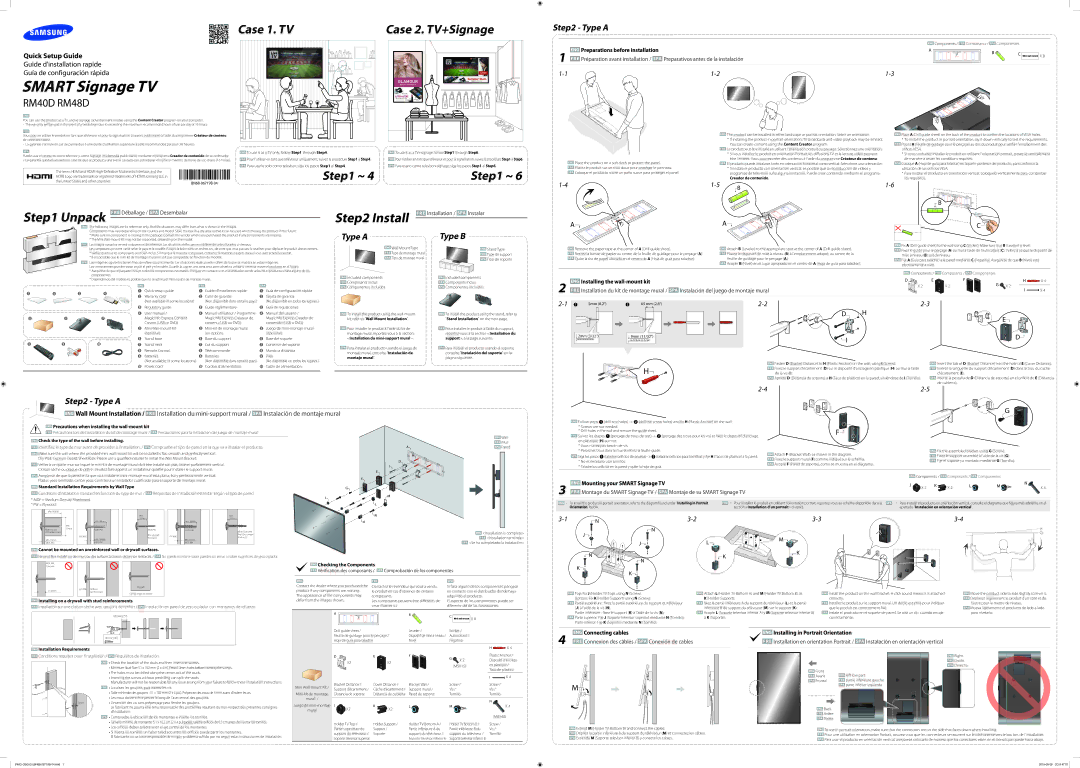
Samsung LH48RMDPLGU/EN manual Components, Creador de contenido, Kit, refer to Wall Mount Installation, 5mm 65 mm

LH48RMDELGW/EN, LH40RMDELGW/EN, LH48RMDPLGU/EN, LH40RMDPLGU/EN specifications

Samsung continues to push the boundaries of display technology with its robust lineup of professional displays, particularly the LH40RMDPLGU/EN, LH48RMDPLGU/EN, LH40RMDELGW/EN, and LH48RMDELGW/EN models. These displays are specifically designed for commercial applications, offering exceptional features and cutting-edge technologies to enhance the viewer experience in retail, corporate, and public spaces.

The LH40RMDPLGU/EN and LH48RMDPLGU/EN models feature a stunning high-definition resolution, ensuring that images and text are sharp and clear. The displays utilize Samsung's advanced LED technology, which not only provides vibrant colors and high contrast ratios but also promotes energy efficiency. This makes them an environmentally friendly choice for businesses looking to minimize their carbon footprint.

One of the standout features of these models is their ability to operate 24/7. This durability ensures that businesses can rely on the displays for continuous use without worrying about downtime. The screens are built with robust components, designed to withstand the rigors of constant operation, making them ideal for digital signage, information displays, and more.

Another significant characteristic of these displays is their versatility in installation. Both wall-mounted and free-standing options allow for flexible placement in various environments. This adaptability means businesses can easily integrate the displays into their existing settings without extensive renovations.

Additionally, these Samsung models come equipped with the Tizen operating system, providing a user-friendly interface for content management. Users can easily upload, schedule, and manage multimedia content remotely, making it convenient to keep messages and advertisements current and engaging. The displays also support a wide range of connectivity options, including HDMI, USB, and more, allowing for seamless integration with other devices and systems.

For users seeking high-performance displays with advanced features, the Samsung LH40RMDPLGU/EN, LH48RMDPLGU/EN, LH40RMDELGW/EN, and LH48RMDELGW/EN models represent a powerful solution. Their combination of vibrant visuals, robust construction, energy efficiency, and user-friendly management options sets a new standard in the world of professional displays. Ideal for any setting that demands reliability and high-quality performance, these Samsung displays are an investment in technology that enhances communication and engages audiences effectively.