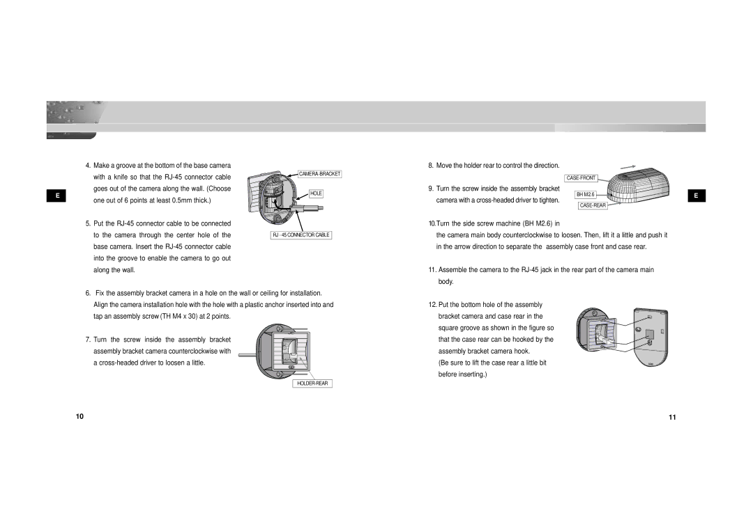
4.Make a groove at the bottom of the base camera with a knife so that the
E
one out of 6 points at least 0.5mm thick.)
5.Put the
![]() CAMERA- BRACKET
CAMERA- BRACKET
HOLE
RJ - 45 CONNECTOR CABLE
8. Move the holder rear to control the direction.
9. Turn the screw inside the assembly bracket |
|
BH M2.6 | E |
camera with a |
|
|
10.Turn the side screw machine (BH M2.6) in |
the camera main body counterclockwise to loosen. Then, lift it a little and push it |
in the arrow direction to separate the assembly case front and case rear. |
11. Assemble the camera to the |
body. |
6.Fix the assembly bracket camera in a hole on the wall or ceiling for installation. Align the camera installation hole with the hole with a plastic anchor inserted into and
tap an assembly screw (TH M4 x 30) at 2 points.
7. Turn the screw inside the assembly bracket assembly bracket camera counterclockwise with a
12. Put the bottom hole of the assembly |
bracket camera and case rear in the square groove as shown in the figure so that the case rear can be hooked by the assembly bracket camera hook.
(Be sure to lift the case rear a little bit before inserting.)
10 | 11 |
