USER’S MANUAL
FCC RF INTERFERENCE STATEMENT
NOTE
This equipment has been tested and found to comply with the limits for a Class B digital device, pursuant to Part 15 of the FCC Rules. These limits are designed to provide reasonable protection against harmful interference in a residential installation. This equipment generates, uses and can radiate radio frequency energy and, if not installed and used in accordance with the instructions, may cause harmful interference to radio communications. However, there is no guarantee that interference will not occur in a particular installation.
If this equipment does cause harmful interference to radio or television reception which can be determined by turning the equipment off and on, the user is encouraged to try to correct the interference by one or more of the following measures.
-Reorient or relocate the receiving antenna. - Increase the separation between the equipment and receiver.
-Connect the equipment into an outlet on a circuit different from that to which the receiver is connected.
-Consult the dealer or an experienced radio, TV technician for help.
-Only shielded interface cable should be used.
Finally, any changes or modifications to the equipment by the user not expressly approved by the grantee or manufacturer could void the users authority to operate such equipment.
• DOC COMPLIANCE NOTICE
This digital apparatus does not exceed the Class B limits for radio noise emissions from digital apparatus set out in the radio interference regulation of Canadian Department of communications.
CONNECTING WITH EXTERNAL EQUIPMENT
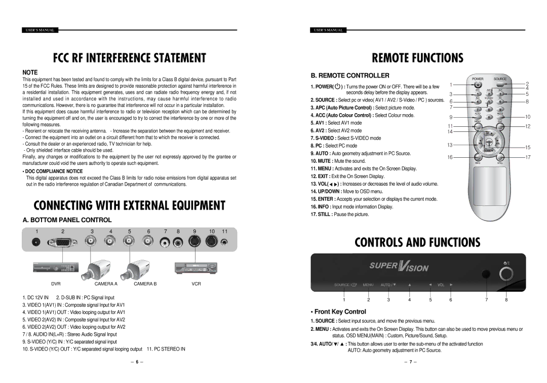
A. BOTTOM PANEL CONTROL
1 | 2 | 3 | 4 | 5 | 6 | 7 | 8 | 9 | 10 | 11 |
DVRCAMERA A CAMERA BVCR
1. DC 12V IN 2.
3.VIDEO 1(AV1) IN : Composite signal Input for AV1
4.VIDEO 1(AV1) OUT : Video looping output for AV1
5.VIDEO 2(AV2) IN : Composite signal Input for AV2
6.VIDEO 2(AV2) OUT : Video looping output for AV2
7/ 8. AUDIO IN(L+R) : Stereo Audio Signal Input
9.
10.
USER’S MANUAL
REMOTE FUNCTIONS
B. REMOTE CONTROLLER
1. POWER(![]() ) : Turns the power ON or OFF. There will be a few seconds delay before the display appears.
) : Turns the power ON or OFF. There will be a few seconds delay before the display appears.
2. SOURCE : Select pc or video( AV1 / AV2 /
3. APC (Auto Picture Control) : Select picture mode.
4. ACC (Auto Colour Control) : Select Colour mode.
5. AV1 : Select AV1 mode
6. AV2 : Select AV2 mode
7.
8. PC : Select PC mode
9. AUTO : Auto geometry adjustment in PC Source.
10.MUTE : Mute the sound.
11.MENU : Activates and exits the On Screen Display.
12.EXIT : Exit the On Screen Display.
13.VOL(![]() ) : Increases or decreases the level of audio volume.
) : Increases or decreases the level of audio volume.
14.UP/DOWN : Move to OSD menu.
15.ENTER : Accepts your selection or displays the current mode.
16.INFO : Input mode information Display.
17.STILL : Pause the picture.
CONTROLS AND FUNCTIONS
1 | 2 | 3 | 4 | 5 | 6 | 7 | 8 |
• Front Key Control
1.SOURCE : Select input source, and move the previous menu.
2.MENU : Activates and exits the On Screen Display. This button can also be used to move previous menu or status. OSD MENU(MAIN) : Custom, Picture/Sound, Setup.
3/4. AUTO/![]() /
/ ![]() : This button allows user to enter the
: This button allows user to enter the
6 |
|
|
| 7 |
|
|