FOR PENDANT MOUNT VERSIONS
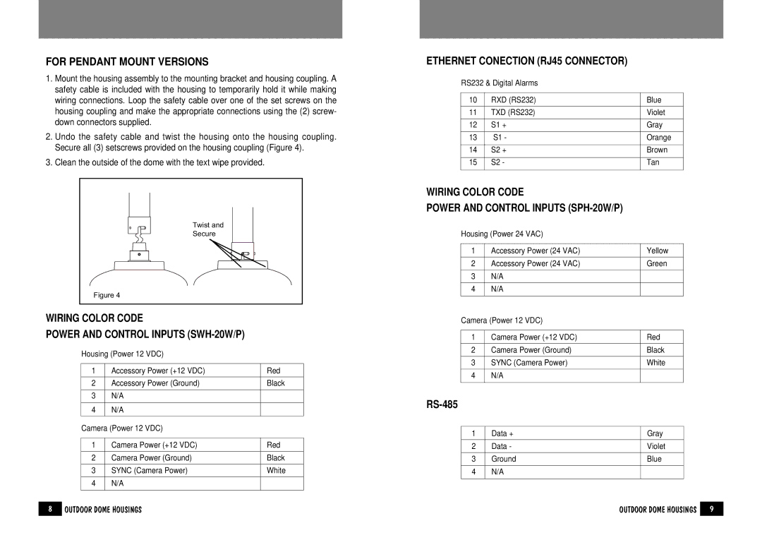
1.Mount the housing assembly to the mounting bracket and housing coupling. A safety cable is included with the housing to temporarily hold it while making wiring connections. Loop the safety cable over one of the set screws on the housing coupling and make the appropriate connections using the (2) screw- down connectors supplied.
2.Undo the safety cable and twist the housing onto the housing coupling. Secure all (3) setscrews provided on the housing coupling (Figure 4).
3.Clean the outside of the dome with the text wipe provided.
Twist and
Secure
Figure 4
WIRING COLOR CODE
POWER AND CONTROL INPUTS (SWH-20W/P)
Housing (Power 12 VDC)
1 | Accessory Power (+12 VDC) | Red |
|
|
|
2 | Accessory Power (Ground) | Black |
|
|
|
3 | N/A |
|
|
|
|
4 | N/A |
|
|
|
|
Camera (Power 12 VDC) |
| |
|
|
|
1 | Camera Power (+12 VDC) | Red |
|
|
|
2 | Camera Power (Ground) | Black |
|
|
|
3 | SYNC (Camera Power) | White |
|
|
|
4 | N/A |
|
|
|
|
ETHERNET CONECTION (RJ45 CONNECTOR)
RS232 & Digital Alarms
10 | RXD (RS232) | Blue | |
|
|
| |
11 | TXD (RS232) | Violet | |
|
|
|
|
12 | S1 | + | Gray |
|
|
| |
13 | S1 - | Orange | |
|
|
|
|
14 | S2 | + | Brown |
|
|
|
|
15 | S2 | - | Tan |
|
|
|
|
WIRING COLOR CODE
POWER AND CONTROL INPUTS (SPH-20W/P)
Housing (Power 24 VAC)
1 | Accessory Power (24 VAC) | Yellow |
|
|
|
2 | Accessory Power (24 VAC) | Green |
|
|
|
3 | N/A |
|
|
|
|
4 | N/A |
|
|
|
|
Camera (Power 12 VDC) |
| |
|
|
|
1 | Camera Power (+12 VDC) | Red |
|
|
|
2 | Camera Power (Ground) | Black |
|
|
|
3 | SYNC (Camera Power) | White |
|
|
|
4 | N/A |
|
|
|
|
1 | Data + | Gray |
|
|
|
2 | Data - | Violet |
|
|
|
3 | Ground | Blue |
|
|
|
4 | N/A |
|
|
|
|
8 | OUTDOOR DOME HOUSINGS | OUTDOOR DOME HOUSINGS | 9 |