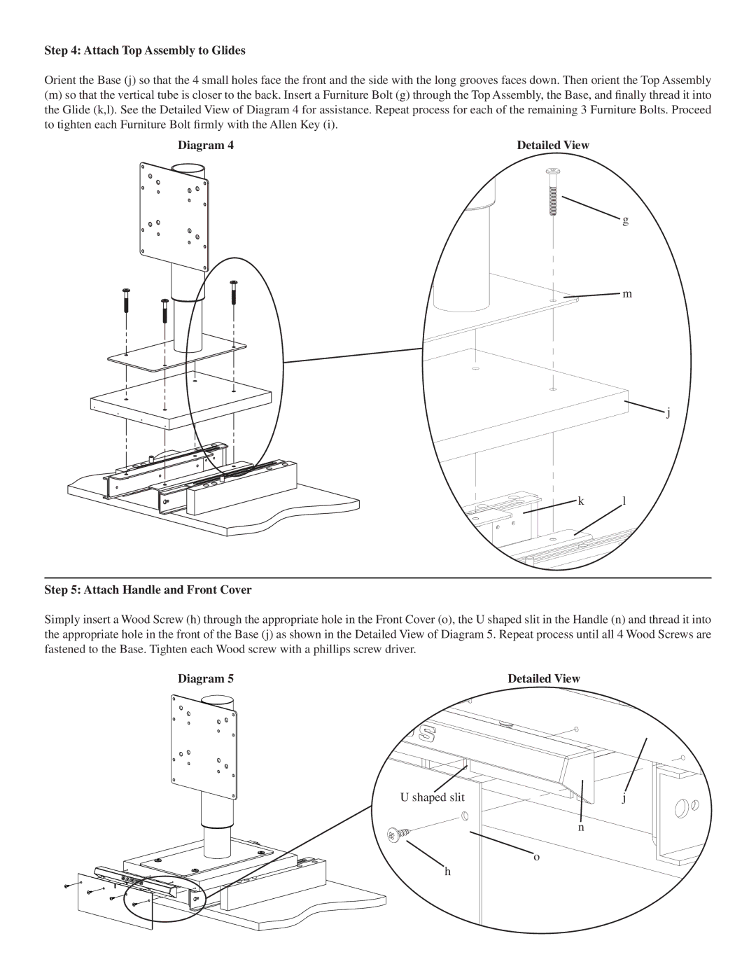
Step 4: Attach Top Assembly to Glides
Orient the Base (j) so that the 4 small holes face the front and the side with the long grooves faces down. Then orient the Top Assembly
(m)so that the vertical tube is closer to the back. Insert a Furniture Bolt (g) through the Top Assembly, the Base, and finally thread it into the Glide (k,l). See the Detailed View of Diagram 4 for assistance. Repeat process for each of the remaining 3 Furniture Bolts. Proceed to tighten each Furniture Bolt firmly with the Allen Key (i).
Diagram 4 | Detailed View |
![]() g
g
![]() m
m
![]() j
j
k l
Step 5: Attach Handle and Front Cover
Simply insert a Wood Screw (h) through the appropriate hole in the Front Cover (o), the U shaped slit in the Handle (n) and thread it into the appropriate hole in the front of the Base (j) as shown in the Detailed View of Diagram 5. Repeat process until all 4 Wood Screws are fastened to the Base. Tighten each Wood screw with a phillips screw driver.
Diagram 5 | Detailed View |
U shaped slit | j |
n
o
h