30 ∝sec
VIDEO OUT
cy
g![]()
RMG
v
| 75% |
YL | 100% |
b | |
| U |
yl | B |
| |
G | Cy |
| mg |
30 ∝sec
VIDEO OUT
After finishing AGC level adjustment, start Hue and chroma adjustment automatically.
Adjustment location: Computer screen
Measuring location: VIDEO OUT
Measuring equipment: Oscilloscope, vectorscope, color bar chart
Subject: Color bar chart (Display the color bar chart at desig- nated picture angle.)
1. Adjust “Adj.Chroma” in the adjustment window.
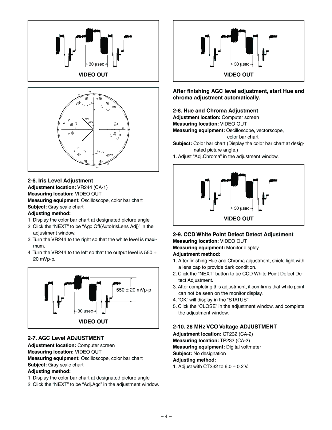
2-6. Iris Level Adjustment
Adjustment location: VR244
Measuring location: VIDEO OUT
Measuring equipment: Oscilloscope, color bar chart
Subject: Gray scale chart
Adjusting method:
1.Display the color bar chart at designated picture angle.
2.Click the “NEXT” to be “Agc Off(AutoIrisLens Adj)” in the adjustment window.
3.Turn the VR244 to the right so that the white level is maxi- mum.
4.Turn the VR244 to the left so that the output level is 550 ± 20
550 ± 20
30 ∝sec
VIDEO OUT
2-7. AGC Level ADJUSTMENT
Adjustment location: Computer screen
Measuring location: VIDEO OUT
Measuring equipment: Oscilloscope, color bar chart
Subject: Gray scale chart
Adjusting method:
1.Display the color bar chart at designated picture angle.
2.Click the “NEXT” to be “Adj.Agc” in the adjustment window.
30 ∝sec
VIDEO OUT
2-9. CCD White Point Defect Detect Adjustment
Measuring location: VIDEO OUT
Measuring equipment: Monitor display
Adjustment method:
1.After finishing Hue and Chroma adjustment, shield light with a lens cap to provide dark condition.
2.Click the “NEXT” button to be CCD White Point Defect De- tect Adjustment.
3.After completing this adjustment, it comfirms that white point can not be seen on the monitor display.
4.“OK” will display in the “STATUS”.
5.Click the “CLOSE” in the adjustment window, and complete the adjustment window.
2-10. 28 MHz VCO Voltage ADJUSTMENT
Adjustment location: CT232
Measuring location: TP232
Measuring equipment: Digital voltmeter
Subject: No designation
Adjusting method:
1. Adjust with CT232 to 6.0 ± 0.2 V.
– 4 –