2. ADJUSTMENT
2-1. ADJUSTMENT CONDITION
1.Use the 5,100K viewer for the subject.
2.Set the trigger signal of oscilloscope to VIDEO OUT, and apply H sync unless specified.
3.Set S3001
4.In adjustments without direction to display charts, shield light with a lens cap to provide dark condition.
5.Connect the video output to a video monitor with an input impedance of 75 Ω.
6.Ground test point is TP200
5,100 K viewer
CCD camera
H
L
CS mount surface
(H + h)2
L =x f – 12.5 mm H x h
L:Distance from CS mount to pattern (mm)
H:Pattern height (mm)
f : Lens focal length (standard 12 mm)
h: Height (4.8 mm) of CCD imaging surface
Note : The video monitor should be an
2-2. PREPARATION
1.Install the adjustment software
2.Use the adjustment tool
3.Use COM1 serial port on the computer.
2-3. TABLE FOR SERVICING TOOLS
Ref. No. | Name | Part code |
|
|
|
Color viewer | ||
|
|
|
Adjustment jig | ||
|
|
|
Calibration software | ||
|
|
|
Chart for color adjustment | ||
|
|
|
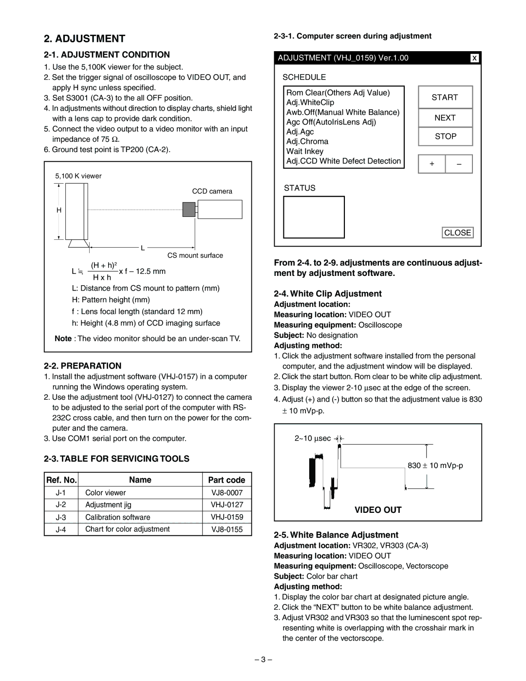
2-3-1. Computer screen during adjustment
|
|
|
|
|
|
|
|
|
ADJUSTMENT (VHJ_0159) Ver.1.00 |
|
|
|
| x |
| ||
SCHEDULE |
|
|
|
|
|
| ||
|
|
|
|
|
|
|
|
|
| Rom Clear(Others Adj Value) |
| START |
|
| |||
| Adj.WhiteClip |
|
|
| ||||
|
|
|
|
|
|
|
| |
| Awb.Off(Manual White Balance) |
|
| NEXT |
|
| ||
| Agc Off(AutoIrisLens Adj) |
|
|
|
| |||
|
|
|
|
|
|
|
| |
| Adj.Agc |
|
| STOP |
|
| ||
| Adj.Chroma |
|
|
|
| |||
|
|
|
|
|
|
|
| |
| Wait Inkey |
|
|
|
|
|
|
|
| Adj.CCD White Defect Detection |
| + |
| – |
|
| |
|
|
|
|
|
|
|
|
|
STATUS
CLOSE
From
Adjustment location:
Measuring location: VIDEO OUT
Measuring equipment: Oscilloscope
Subject: No designation
Adjusting method:
1.Click the adjustment software installed from the personal computer, and the adjustment window will be displayed.
2.Click the start button. Rom clear to be white clip adjustment.
3.Display the viewer
4.Adjust (+) and
±10
2~10 ∝sec ![]()
830 ± 10
VIDEO OUT
2-5. White Balance Adjustment
Adjustment location: VR302, VR303
Measuring location: VIDEO OUT
Measuring equipment: Oscilloscope, Vectorscope
Subject: Color bar chart
Adjusting method:
1.Display the color bar chart at designated picture angle.
2.Click the “NEXT” button to be white balance adjustment.
3.Adjust VR302 and VR303 so that the luminescent spot rep- resenting white is overlapping with the crosshair mark in the center of the vectorscope.
– 3 –