![]() WARNING
WARNING
Fire Risk
•Comply with all minimum clearances to combustibles as specifi ed.
Failure to comply may cause fi re.
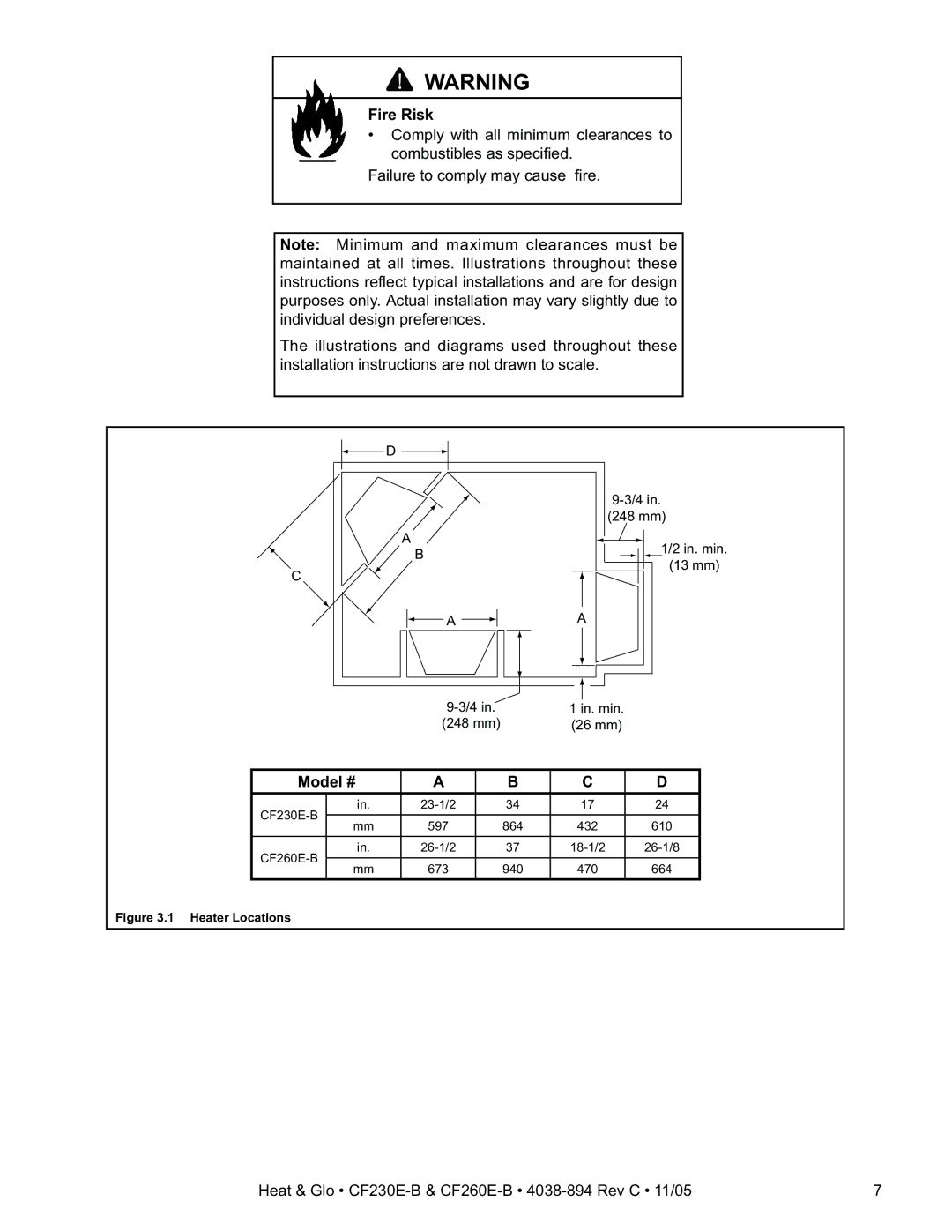
Note: Minimum and maximum clearances must be maintained at all times. Illustrations throughout these instructions refl ect typical installations and are for design purposes only. Actual installation may vary slightly due to individual design preferences.
The illustrations and diagrams used throughout these installation instructions are not drawn to scale.
D
(248 mm)
A
B
C
1/2 in. min.
(13 mm)
A ![]() A
A
1 in. min. | |
(248 mm) | (26 mm) |
Model # | A | B | C | D | ||
in. | 34 | 17 | 24 | |||
mm | 597 | 864 | 432 | 610 | ||
| ||||||
in. | 37 | |||||
|
|
|
|
| ||
mm | 673 | 940 | 470 | 664 | ||
| ||||||
Figure 3.1 Heater Locations
Heat & Glo • | 7 |
