Scag Power Equipment MAG manual Throttle Control Linkage Adjustment, Cutter Brake Linkage, Section

Models: MAG

1 66
Download 66 pages 24.09 Kb
Page 23
Image 23
6.3THROTTLE CONTROL LINKAGE ADJUSTMENT

Section 6

-NOTE-

If you turn the nut too much, you will com- press the spring, making too much end play. Go to step 4.

4.If the drive wheels rotate in rearward travel direction, turn the adjustment bolt (Figure 6-1) clockwise until rotation stops. If the drive wheels rotate in the for- ward travel direction, turn the adjusting bolt counter- clockwise until rotation stops.

5.Check the adjustment of the right foot pedal for full forward speed. The bottom of the foot pedal should be 1/4 inch from the top of the foot plate (See Figure 6-1) when the pump is stroked in the full forward position.

To make an adjustment, loosen the jam nut at the pump control bellcrank (Figure 6-1). Depress the foot pedal and turn the control rod until 1/4 inch is obtained between the bottom of the foot pedal and the top of the foot plate. Tighten the jam nut.

6.Start the engine. The drive wheels should rotate only when the forward/reverse foot pedal is depressed.

6.3THROTTLE CONTROL LINKAGE ADJUSTMENT

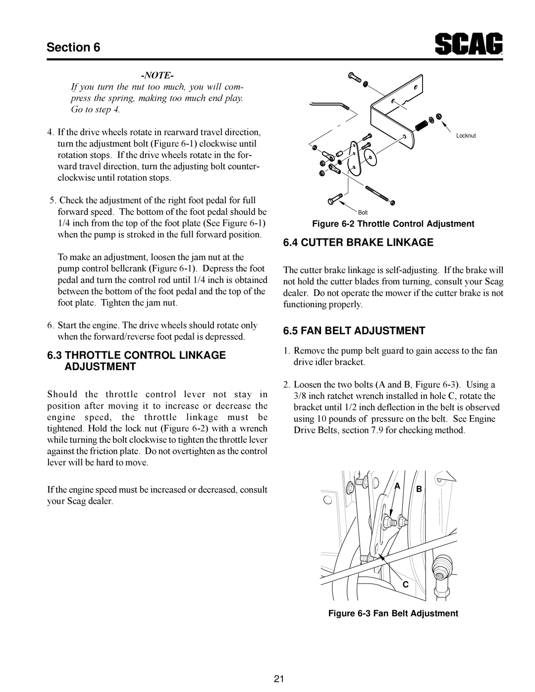
Should the throttle control lever not stay in position after moving it to increase or decrease the engine speed, the throttle linkage must be tightened. Hold the lock nut (Figure 6-2) with a wrench while turning the bolt clockwise to tighten the throttle lever against the friction plate. Do not overtighten as the control lever will be hard to move.

Locknut

Bolt

Figure 6-2 Throttle Control Adjustment

6.4 CUTTER BRAKE LINKAGE

The cutter brake linkage is self-adjusting. If the brake will not hold the cutter blades from turning, consult your Scag dealer. Do not operate the mower if the cutter brake is not functioning properly.

6.5 FAN BELT ADJUSTMENT

1.Remove the pump belt guard to gain access to the fan drive idler bracket.

2.Loosen the two bolts (A and B, Figure 6-3). Using a 3/8 inch ratchet wrench installed in hole C, rotate the bracket until 1/2 inch deflection in the belt is observed using 10 pounds of pressure on the belt. See Engine Drive Belts, section 7.9 for checking method.

If the engine speed must be increased or decreased, consult

A

B


your Scag dealer.


C

Figure 6-3 Fan Belt Adjustment

21

Page 23
Image 23
Scag Power Equipment MAG manual Throttle Control Linkage Adjustment, Cutter Brake Linkage, Fan Belt Adjustment, Section