F. | DC CONNECTION PRECAUTION |
Connect and disconnect the DC output connections only after removing the AC cord from the electric outlet.
G. | DC CONNECTION PROCEDURE |
When charging battery(ies) in boat, take care to determine the battery type and which pole is ground. To reduce risk of a spark near battery, follow these general steps when battery is inside boat. WARNING: A spark near the battery may cause battery explosion.
1.Position AC power cord and DC charging cords to reduce risk of damage.
2.Stay clear of fan blades, belts, pulleys, and other parts that can cause injury.
3.Check polarity of battery posts. Battery case will be marked to indicate each post’s polarity: POSITIVE (POS, P, +) and NEGATIVE (NEG, N,
4.Determine which post of battery is ground.
5.Connect POSITIVE (RED) ring terminal from battery charger to POSITIVE (POS, P, +) post of battery.
6.Connect NEGATIVE (BLACK) ring terminal to NEGATIVE (NEG, N,
7.When disconnecting the charger, disconnect the AC power cord from the electric outlet first.
8.While disconnecting output leads from the batteries, always do so in reverse order of the connection procedure.
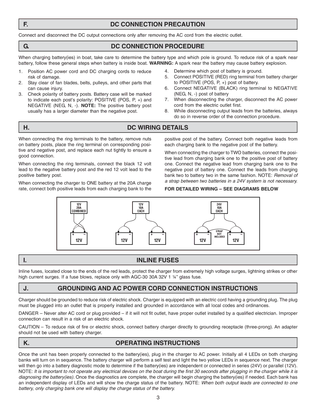
H. | DC WIRING DETAILS |
When connecting the ring terminals to the battery, remove nuts on battery posts, place the ring terminal on corresponding posi- tive and negative post, and replace each nut tightly to ensure a good connection.
When connecting the ring terminals, connect the black 12 volt lead to the negative battery post and the red 12 volt lead to the positive battery post.
When connecting the charger to ONE battery at the 20A charge rate, connect both positive leads from each charging bank to the
positive post of the battery. Connect both negative leads from each charging bank to the negative post of the battery.
When connecting the charger to TWO batteries, connect the posi- tive lead from charging bank one to the positive post of battery one. Connect the negative lead from charging bank one to the negative post of battery one. Connect the leads from charging bank two to battery two in the same fashion. NOTE: Removal of a strap between two batteries in a 24V system is not necessary.
FOR DETAILED WIRING – SEE DIAGRAMS BELOW
12V
20A
COMBINED
12V
10A
EACH
24V
10A
EACH
+ | – |
| 12V |
+ | – |
| 12V |
+ | – |
| 12V |
+ | – |
| 12V |
STRAP
NOT
INCLUDED
+ | – |
| 12V |
I. | INLINE FUSES |
Inline fuses, located close to the ends of the red leads, protect the charger from extremely high voltage surges, lightning strikes or other high current surges. If a fuse blows, replace only with
J.GROUNDING AND AC POWER CORD CONNECTION INSTRUCTIONS
Charger should be grounded to reduce risk of electric shock. Charger is equipped with an electric cord having a grounding plug. The plug must be plugged into an outlet that is properly installed and grounded in accordance with all local codes and ordinances.
DANGER – Never alter AC cord or plug provided – if it will not fit outlet, have proper outlet installed by a qualified electrician. Improper connection can result in a risk of an electric shock.
CAUTION – To reduce risk of fire or electric shock, connect battery charger directly to grounding receptacle
K. | OPERATING INSTRUCTIONS |
Once the unit has been properly connected to the battery(ies), plug in the charger to AC power. Initially all 4 LEDs on both charging banks will turn on in sequence. The battery charger will perform a self test and light the two yellow LEDs in sequence next. The charger will then go into a battery diagnostic mode to determine if the battery(ies) are independent or connected in series (24V) or parallel (12V). NOTE: It is important to not operate any electrical devices on the boat during the first 30 seconds after plugging in the charger while it is diagnosing the battery(ies). Once the diagnostics are complete, the charger will begin charging the battery(ies) if needed. Each bank has an independent display of LEDs and will show the charge status of the battery. NOTE: When both output leads are connected to one battery, only charging bank one will display the charge status of the battery.
3