4.2Serial ATA device plug connector pin definitions
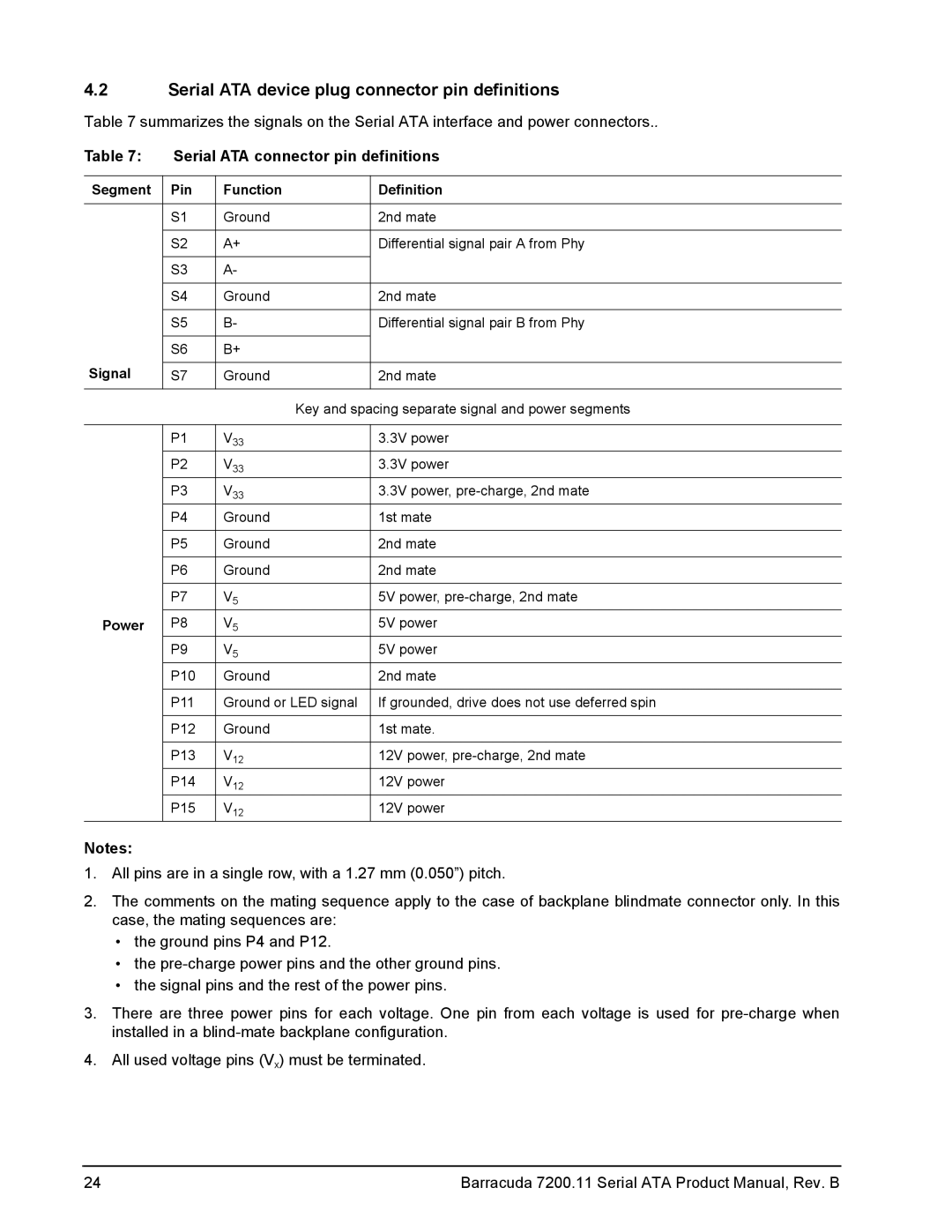
Table 7 summarizes the signals on the Serial ATA interface and power connectors..
Table 7: | Serial ATA connector pin definitions | ||
|
|
|
|
Segment | Pin | Function | Definition |
|
|
|
|
| S1 | Ground | 2nd mate |
|
|
|
|
| S2 | A+ | Differential signal pair A from Phy |
|
|
|
|
| S3 | A- |
|
|
|
|
|
| S4 | Ground | 2nd mate |
|
|
|
|
| S5 | B- | Differential signal pair B from Phy |
|
|
|
|
| S6 | B+ |
|
Signal |
|
|
|
S7 | Ground | 2nd mate | |
|
|
|
|
|
| Key and spacing separate signal and power segments | |
|
|
|
|
| P1 | V33 | 3.3V power |
| P2 | V33 | 3.3V power |
| P3 | V33 | 3.3V power, |
| P4 | Ground | 1st mate |
|
|
|
|
| P5 | Ground | 2nd mate |
|
|
|
|
| P6 | Ground | 2nd mate |
|
|
|
|
| P7 | V5 | 5V power, |
Power | P8 | V5 | 5V power |
| P9 | V5 | 5V power |
| P10 | Ground | 2nd mate |
|
|
|
|
| P11 | Ground or LED signal | If grounded, drive does not use deferred spin |
|
|
|
|
| P12 | Ground | 1st mate. |
|
|
|
|
| P13 | V12 | 12V power, |
| P14 | V12 | 12V power |
| P15 | V12 | 12V power |
Notes:
1.All pins are in a single row, with a 1.27 mm (0.050”) pitch.
2.The comments on the mating sequence apply to the case of backplane blindmate connector only. In this case, the mating sequences are:
•the ground pins P4 and P12.
•the
•the signal pins and the rest of the power pins.
3.There are three power pins for each voltage. One pin from each voltage is used for
4.All used voltage pins (Vx) must be terminated.
24 | Barracuda 7200.11 Serial ATA Product Manual, Rev. B |