Serial ATA Interface | www.seagate.com |
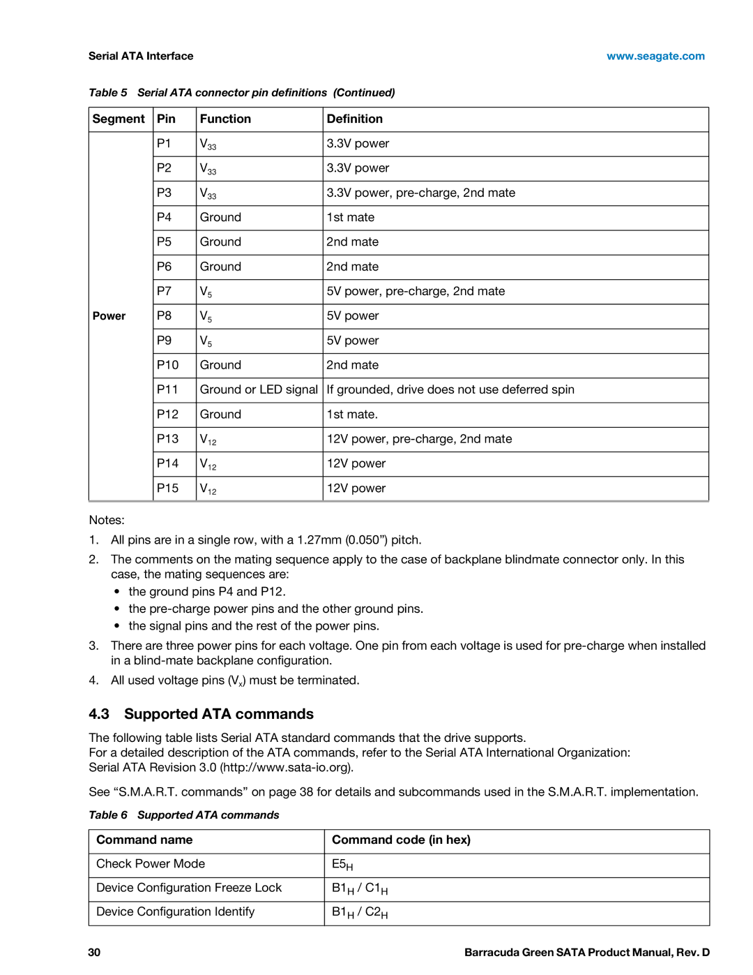
Table 5 Serial ATA connector pin definitions (Continued)
Segment | Pin | Function | Definition |
|
|
|
|
| P1 | V33 | 3.3V power |
| P2 | V33 | 3.3V power |
| P3 | V33 | 3.3V power, |
| P4 | Ground | 1st mate |
|
|
|
|
| P5 | Ground | 2nd mate |
|
|
|
|
| P6 | Ground | 2nd mate |
|
|
|
|
| P7 | V5 | 5V power, |
|
|
|
|
Power | P8 | V5 | 5V power |
|
|
|
|
| P9 | V5 | 5V power |
| P10 | Ground | 2nd mate |
|
|
|
|
| P11 | Ground or LED signal | If grounded, drive does not use deferred spin |
|
|
|
|
| P12 | Ground | 1st mate. |
|
|
|
|
| P13 | V12 | 12V power, |
| P14 | V12 | 12V power |
| P15 | V12 | 12V power |
Notes:
1.All pins are in a single row, with a 1.27mm (0.050”) pitch.
2.The comments on the mating sequence apply to the case of backplane blindmate connector only. In this case, the mating sequences are:
•the ground pins P4 and P12.
•the
•the signal pins and the rest of the power pins.
3.There are three power pins for each voltage. One pin from each voltage is used for
4.All used voltage pins (Vx) must be terminated.
4.3Supported ATA commands
The following table lists Serial ATA standard commands that the drive supports.
For a detailed description of the ATA commands, refer to the Serial ATA International Organization: Serial ATA Revision 3.0
See “S.M.A.R.T. commands” on page 38 for details and subcommands used in the S.M.A.R.T. implementation.
Table 6 Supported ATA commands
Command name | Command code (in hex) |
|
|
Check Power Mode | E5H |
Device Configuration Freeze Lock | B1H / C1H |
Device Configuration Identify | B1H / C2H |
30 | Barracuda Green SATA Product Manual, Rev. D |
