Cheetah 10K.7 FC Installation Guide

ST3300007FC/FCV, ST3146707FC/FCV, ST373207FC/FCV

Publication Number: 100260920, Rev. A, March 2004

Handling precautions/Electrostatic discharge protection

Disc drives are fragile. Do not drop or jar the drive. Handle the drive only by the edges or frame.

Drive electronics are extremely sensitive to static electricity. Keep the drive in its antistatic container until you are ready to install it. Wear a wrist strap and cable connected to ground. Discharge static from all items near or that will contact the drive. Never use an ohmmeter on any circuit boards.

Turn off the power to the host system during installation.

Always use forced-air ventilation when operating the drive.

Use caution when troubleshooting a unit that has voltages present.

Do not disassemble the drive; doing so voids the warranty.

Return the entire drive for depot service if any part is defective.

Do not apply pressure or attach labels to the circuit board or to the top of the drive.

Electromagnetic compliance

See the Safety and Regulatory Agency Specifications page, part number 75789512, which was shipped with this installation guide.

Drive characteristics


ST3300007FC

ST3146707FC

ST373207FC

Formatted capacity

300.0 Gbytes

146.8 Gbytes

73.4 Gbytes

Total # of data blocks

585,937,500

286,749,488

143,374,744


(22ECB25Ch)

(11177330h)

(88BB998h)

Cylinders (user accessible) 90,773


90,773


90,773


Heads (user accessible)

8


4


2


Disc rotation +/- 5%

10,000 RPM

10,000 RPM

10,000 RPM

Operating voltages

+5V

+12V

+5V

+12V

+5V

+12V

Typical operating


current (amps) 1 Gbit

0.93

1.10

0.82

0.86

0.91

0.74

What you need

Screwdriver and four 6-32 UNC drive mounting screws

Forced-air ventilation to provide adequate drive cooling

Host system with Fibre Channel host adapter or backplane

Installation instructions

1. Mount the drive in the host system carrier or tray

Most Fibre Channel host systems (including enclosures) provide a way to insert the drive using a carrier or tray which allows the drive to be hot- plugged into the system’s Fibre Channel 40-pin single connector attach- ment (FC-SCA).

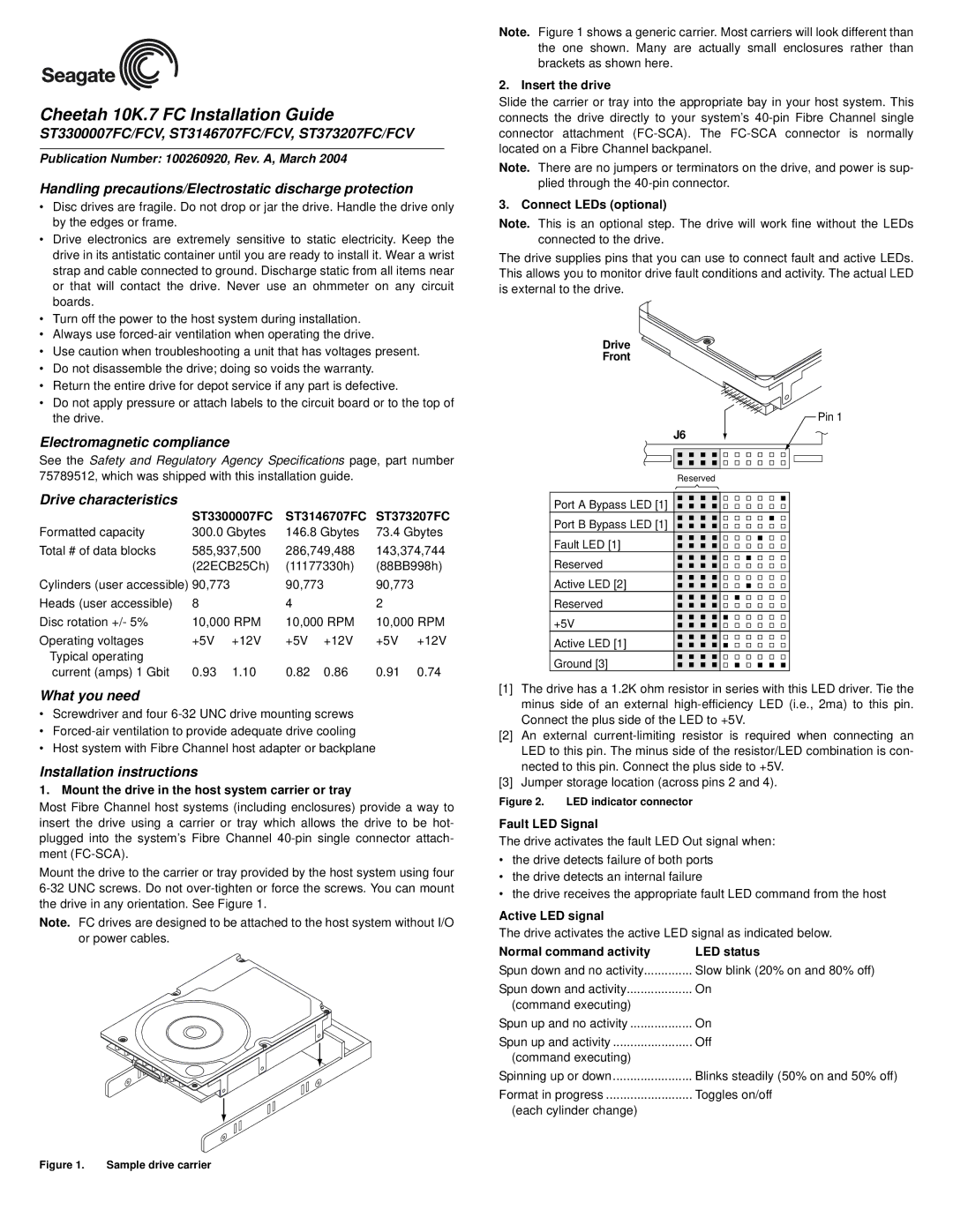
Mount the drive to the carrier or tray provided by the host system using four 6-32 UNC screws. Do not over-tighten or force the screws. You can mount the drive in any orientation. See Figure 1.

Note. FC drives are designed to be attached to the host system without I/O or power cables.

Note. Figure 1 shows a generic carrier. Most carriers will look different than the one shown. Many are actually small enclosures rather than brackets as shown here.

2. Insert the drive

Slide the carrier or tray into the appropriate bay in your host system. This connects the drive directly to your system’s 40-pin Fibre Channel single connector attachment (FC-SCA). The FC-SCA connector is normally located on a Fibre Channel backpanel.

Note. There are no jumpers or terminators on the drive, and power is sup- plied through the 40-pin connector.

3. Connect LEDs (optional)

Note. This is an optional step. The drive will work fine without the LEDs connected to the drive.

The drive supplies pins that you can use to connect fault and active LEDs. This allows you to monitor drive fault conditions and activity. The actual LED is external to the drive.

Drive

Front

Pin 1

J6

Reserved

Port A Bypass LED [1]

Port B Bypass LED [1]

Fault LED [1]

Reserved

Active LED [2]

Reserved

+5V

Active LED [1]

Ground [3]

[1]The drive has a 1.2K ohm resistor in series with this LED driver. Tie the minus side of an external high-efficiency LED (i.e., 2ma) to this pin. Connect the plus side of the LED to +5V.

[2]An external current-limiting resistor is required when connecting an LED to this pin. The minus side of the resistor/LED combination is con- nected to this pin. Connect the plus side to +5V.

[3]Jumper storage location (across pins 2 and 4).

Figure 2. LED indicator connector

Fault LED Signal

The drive activates the fault LED Out signal when:

the drive detects failure of both ports

the drive detects an internal failure

the drive receives the appropriate fault LED command from the host

Active LED signal

The drive activates the active LED signal as indicated below.

Normal command activity

LED status

Spun down and no activity

Slow blink (20% on and 80% off)

Spun down and activity

On

(command executing)


Spun up and no activity

On

Spun up and activity

Off

(command executing)


Spinning up or down

Blinks steadily (50% on and 50% off)

Format in progress

Toggles on/off

(each cylinder change)


Figure 1. Sample drive carrier

Page 1
Image 1
Seagate installation instructions ST3300007FC/FCV, ST3146707FC/FCV, ST373207FC/FCV, Electromagnetic compliance

ST3146707FC/FCV, ST3300007FC/FCV, ST373207FC/FCV specifications

Seagate's ST3300007FC/FCV, ST3146707FC/FCV, and ST373207FC/FCV are a series of high-performance hard disk drives designed primarily for enterprise environments. Renowned for their reliability and speed, these models are optimized for data-intensive applications, making them suitable for server storage, data warehouses, and high-capacity backup solutions.

The ST3300007FC/FCV model offers a capacity of 3TB, providing ample room for large datasets. It utilizes a 7200 RPM spindle speed, which facilitates quick data access and an enhanced user experience. One of the standout features is its support for Serial Attached SCSI (SAS) interface, enabling high transfer rates and increased reliability compared to traditional SATA drives. This release also employs Seagate's Thermal Fly Height Compensation technology, which improves performance and reduces the risk of data loss due to thermal expansion.

Similarly, the ST3146707FC/FCV is tailored for enterprise applications, offering 1.4TB of storage. Its advanced error correction capabilities ensure data integrity over extended usage periods. This model, like others in this line, incorporates PowerBalance technology, which allows for energy-efficient operation under various workloads without sacrificing performance. With a mean time between failures (MTBF) rated at 1.4 million hours, businesses can rely on these drives for their mission-critical applications.

The ST373207FC/FCV model boasts a 7200 RPM spindle speed as well, but with a capacity of 732GB. This smaller yet efficient drive is designed for tasks requiring faster response times, such as database transactions and caching. The dual port functionality of the SAS interface enhances redundancy and failover capabilities, providing uninterrupted operational efficiency.

Each model's implementation of Seagate's Enhanced Error Correction Code (ECC) not only boosts data reliability but also minimizes downtime, which is critical in enterprise settings. The drives are also designed with vibration tolerance in mind, making them ideal for use in multi-drive environments, where physical space can lead to interference.

All three of these Seagate drives embody a commitment to performance, reliability, and data integrity. They are engineered for demanding environments, offering the scalability that organizations require to handle growing data needs. Overall, the ST3300007FC/FCV, ST3146707FC/FCV, and ST373207FC/FCV stand out as robust options for enterprises aiming to enhance their data storage solutions.