Degrees C ambient.
[2]For +12 V, a
[3]See +12V current profile in Figures 2, 3, and 4.
[4]This condition occurs after OOB and Speed Negotiation completes but before the drive has received the Notify Spinup primitive.
[5]See paragraph 6.2.1, "Conducted noise immunity." Specified voltage tolerance includes ripple, noise, and transient response.
[6]During idle, the drive heads are relocated every 60 seconds to a random location within the band from
General DC power requirement notes.
1.Minimum current loading for each supply voltage is not less than 1.7% of the maximum operating current shown.
2.The +5V and +12V supplies should employ separate ground returns.
3.Where power is provided to multiple drives from a common supply, careful consideration for individual drive power requirements should be noted. Where multiple units are powered on simultaneously, the peak starting current must be available to each device.
4.Parameters, other than spindle start, are measured after a
5.No terminator power.
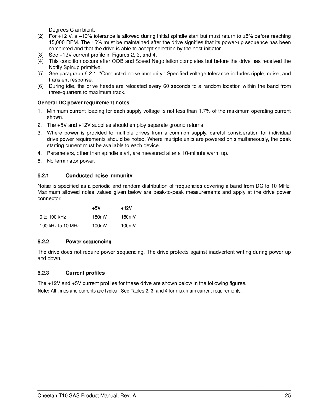
6.2.1Conducted noise immunity
Noise is specified as a periodic and random distribution of frequencies covering a band from DC to 10 MHz. Maximum allowed noise values given below are
| +5V | +12V |
0 to 100 kHz | 150mV | 150mV |
100 kHz to 10 MHz | 100mV | 100mV |
6.2.2Power sequencing
The drive does not require power sequencing. The drive protects against inadvertent writing during
6.2.3Current profiles
The +12V and +5V current profiles for these drive are shown below in the following figures.
Note: All times and currents are typical. See Tables 2, 3, and 4 for maximum current requirements.
Cheetah T10 SAS Product Manual, Rev. A | 25 |