Cheetah 4LP FC Installation Guide, Rev. B | 21 |
|
|
Schraube nicht ohne Widerstand einschrauben läßt, sind die Gewinde nicht korrekt aneinander ausgerichtet.
| N |
[1] | P |
| A |
R |
|
F |
|
| D |
| G |
| E |
[3]
C
![]()
![]()
![]() M
M
L
Notes:
[2]
K
J
[4]
B
[5]
H
S
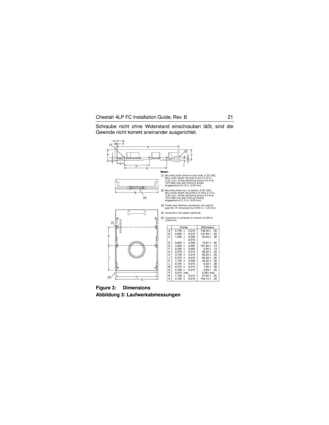
[1]Mounting holes three on each side,
(3.81 mm). Screw tightening torque 6.0
[2]Mounting holes four on bottom,
[3]Power and interface connectors can extend past the “A” dimension by 0.040 in. (1.02 mm).
[4]Decorative front panel (optional).
[5]Connector is centered on module ±0.020 in. (.508 mm).
| Inches |
| Millimeters | |||
A | 5.750 | ± | 0.010 | 146.05 | ± | .25 |
B | 4.000 | ± | 0.010 | 101.60 | ± | .25 |
C | 1.000 | + | 0.026 | 25.40 | ± | .38 |
|
| – | 0.010 |
|
|
|
D | 0.625 | ± | 0.020 | 15.87 | ± | .50 |
E | 4.000 | ± | 0.005 | 101.60 | ± | .13 |
F | 0.250 | ± | 0.005 | 6.35 | ± | .13 |
G | 2.375 | ± | 0.010 | 60.32 | ± | .25 |
H | 3.750 | ± | 0.010 | 95.25 | ± | .25 |
J | 2.370 | ± | 0.010 | 60.20 | ± | .25 |
K | 1.750 | ± | 0.020 | 44.45 | ± | .50 |
L | 0.181 | ± | 0.015 | 4.32 | ± | .38 |
M | 0.275 | ± | 0.015 | 7.00 | ± | .38 |
N | 0.190 | ± | 0.010 | 4.83 | ± | .25 |
P | 0.015 | max | 0.381 max | |||
R | 1.100 | ± | 0.010 | 27.94 | ± | .25 |
S | 4.100 | ± | 0.010 | 104.14 | ± | .25 |
|
|
|
|
|
|
|