9.5.8Active LED Out

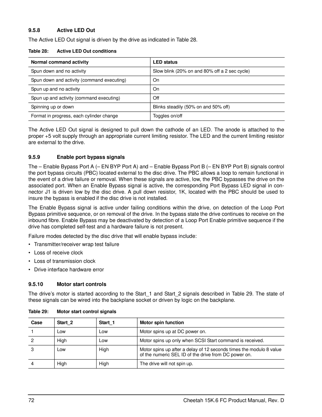
The Active LED Out signal is driven by the drive as indicated in Table 28.

Table 28: Active LED Out conditions

Normal command activity

LED status


Spun down and no activity

Slow blink (20% on and 80% off a 2 sec cycle)


Spun down and activity (command executing)

On


Spun up and no activity

On


Spun up and activity (command executing)

Off


Spinning up or down

Blinks steadily (50% on and 50% off)


Format in progress, each cylinder change

Toggles on/off


The Active LED Out signal is designed to pull down the cathode of an LED. The anode is attached to the proper +5 volt supply through an appropriate current limiting resistor. The LED and the current limiting resistor are external to the drive.

9.5.9Enable port bypass signals

The – Enable Bypass Port A (– EN BYP Port A) and – Enable Bypass Port B (– EN BYP Port B) signals control the port bypass circuits (PBC) located external to the disc drive. The PBC allows a loop to remain functional in the event of a drive failure or removal. When these signals are active, low, the PBC bypasses the drive on the associated port. When an Enable Bypass signal is active, the corresponding Port Bypass LED signal in con- nector J1 is driven low by the disc drive. A pull down resistor, 1K, located with the PBC should be used to insure the bypass is enabled if the disc drive is not installed.

The Enable Bypass signal is active under failing conditions within the drive, on detection of the Loop Port Bypass primitive sequence, or on removal of the drive. In the bypass state the drive continues to receive on the inbound fibre. Enable Bypass may be deactivated by detection of a Loop Port Enable primitive sequence if the drive has completed self-test and a hardware failure is not present.

Failure modes detected by the disc drive that will enable bypass include:

Transmitter/receiver wrap test failure

Loss of receive clock

Loss of transmission clock

Drive interface hardware error

9.5.10Motor start controls

The drive’s motor is started according to the Start_1 and Start_2 signals described in Table 29. The state of these signals can be wired into the backplane socket or driven by logic on the backplane.

Table 29:

Motor start control signals


Case

Start_2

Start_1

Motor spin function


1

Low

Low

Motor spins up at DC power on.


2

High

Low

Motor spins up only when SCSI Start command is received.


3

Low

High

Motor spins up after a delay of 12 seconds times the modulo 8 value


of the numeric SEL ID of the drive from DC power on.


4

High

High

The drive will not spin up.


72

Cheetah 15K.6 FC Product Manual, Rev. D

Page 78
Image 78
Seagate ST3450856FC manual Active LED Out, Enable port bypass signals, Motor start controls

ST3450856FC specifications

The Seagate ST3146356FC, ST3300656FC, and ST3450856FC are hard disk drives designed for enterprise storage solutions, showcasing Seagate’s commitment to performance, reliability, and advanced technology in the data storage sector. These drives cater primarily to the needs of data centers and businesses requiring robust data management capabilities.

The ST3146356FC is notable for its 146GB capacity, 3.5-inch form factor, and 10,000 RPM spindle speed. It employs Serial Attached SCSI (SAS) interface technology, which ensures high data transfer rates and reliable connectivity. This model is designed to handle a multitude of demanding applications, such as online transaction processing and enterprise resource planning, requiring fast access to data and minimized latency.

The ST3300656FC, with a capacity of 300GB, continues the trend of high performance set by its predecessor. This drive also features the 10,000 RPM spindle speed and SAS interface, providing enhanced data throughput and optimized performance for intensive workloads. The drive is built with advanced error recovery features that enhance data integrity and reliability, making it suitable for critical applications where data loss is unacceptable.

The ST3450856FC offers even greater capacity, with a robust 450GB storage option. Like the other models, it operates at 10,000 RPM and utilizes the SAS interface. This drive is designed for scalability, ensuring that it can meet the evolving storage demands of enterprises. It is also equipped with sophisticated technologies such as Seagate's Enhanced S.M.A.R.T. (Self-Monitoring, Analysis, and Reporting Technology), providing continual monitoring of the drive’s health and performance metrics.

All three models share key characteristics, including advanced thermal and power management technologies that help maintain optimal operating temperatures and reduce energy consumption. This is crucial in data center environments where maximizing efficiency is vital for operational cost management. Additionally, Seagate's commitment to low acoustic noise levels ensures quieter operation, which is beneficial in environments where sound levels must be controlled.

In summary, the Seagate ST3146356FC, ST3300656FC, and ST3450856FC drives are engineered for enterprise environments demanding high reliability, speed, and capacity. Their advanced technologies, including SAS interface and enhanced error management systems, make these drives ideal for critical applications in data-intensive sectors. With reinforced durability, effectiveness in managing large volumes of data, and a focus on energy efficiency, these drives symbolize the pinnacle of Seagate's storage innovations for enterprise solutions.