4.4Drive mounting
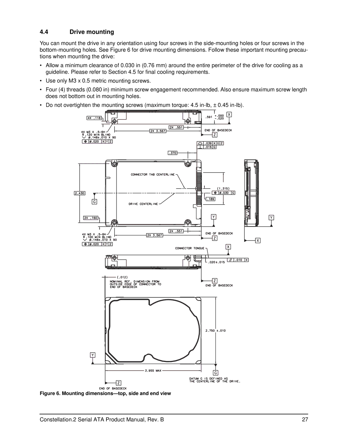
You can mount the drive in any orientation using four screws in the
•Allow a minimum clearance of 0.030 in (0.76 mm) around the entire perimeter of the drive for cooling as a guideline. Please refer to Section 4.5 for final cooling requirements.
•Use only M3 x 0.5 metric mounting screws.
•Four (4) threads (0.080 in) minimum screw engagement recommended. Also ensure maximum screw length does not bottom out in mounting holes.
•Do not overtighten the mounting screws (maximum torque: 4.5
Figure 6. Mounting dimensions—top, side and end view
Constellation.2 Serial ATA Product Manual, Rev. B | 27 |