Table 17: Transmitter signal characteristics
Signal characteristica
Units
1.5 Gbps
3.0 Gbps
aAll tests in this table shall be performed with
bThe skew measurement shall be made at the midpoint of the transition with a repeating 0101b pattern on the physical link. The same stable trigger, coherent to the data stream, shall be used for both the Tx+ and Tx- signals. Skew is defined as the time difference between the means of the midpoint crossing times of the Tx+ signal and the Tx- signal.
cThe transmitter off voltage is the maximum A.C. voltage measured at compliance points when the transmitter is unpowered or transmitting D.C. idle (e.g., during idle time of an OOB signal).
dRise/fall times are measured from 20 % to 80 % of the transition with a repeating 0101b pattern on the physical link.
eThe maximum difference between the V+ and V- A.C. RMS transmitter amplitudes measured on a CJTPAT test pattern (see 9.5.2.3.3) into the test load shown in figure 20, as a percentage of the average of the V+ and V- A.C. RMS amplitudes.
fThe maximum difference in the average differential voltage (D.C. offset) component between the burst times and the idle times of an OOB signal.
gThe maximum difference in the average of the common mode voltage between the burst times and the idle times of an OOB signal.
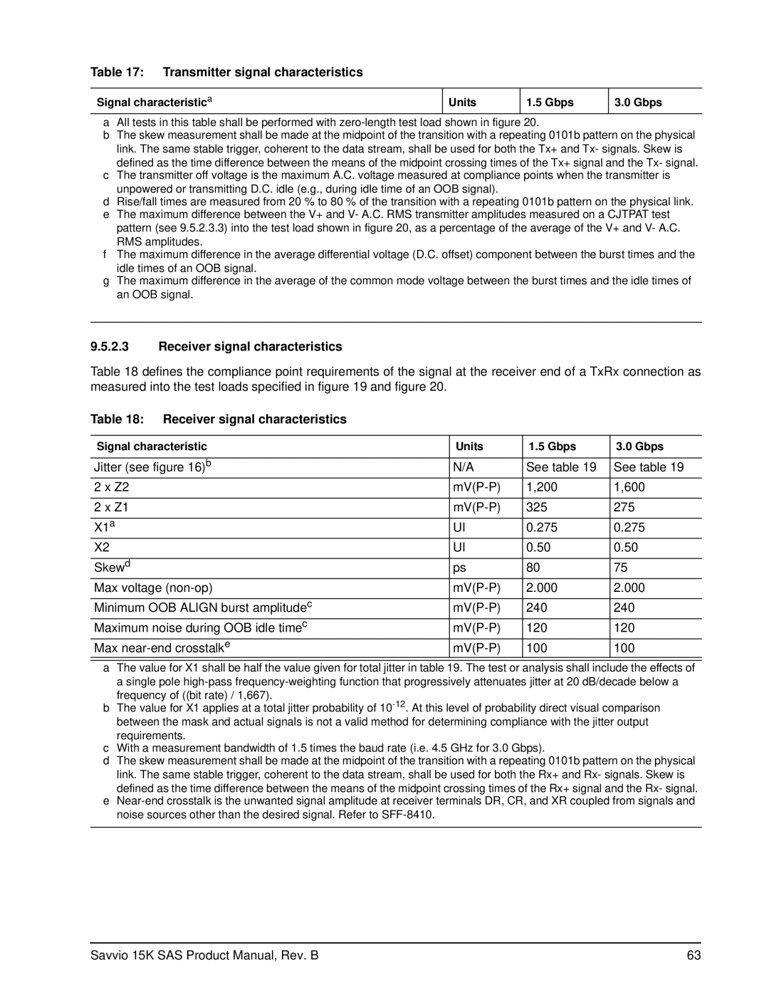
9.5.2.3Receiver signal characteristics
Table 18 defines the compliance point requirements of the signal at the receiver end of a TxRx connection as measured into the test loads specified in figure 19 and figure 20.
Table 18: Receiver signal characteristics
Signal characteristic | Units | 1.5 Gbps | 3.0 Gbps |
|
|
|
|
Jitter (see figure 16)b | N/A | See table 19 | See table 19 |
2 x Z2 | 1,200 | 1,600 | |
|
|
|
|
2 x Z1 | 325 | 275 | |
|
|
|
|
X1a | UI | 0.275 | 0.275 |
X2 | UI | 0.50 | 0.50 |
|
|
|
|
Skewd | ps | 80 | 75 |
Max voltage | 2.000 | 2.000 | |
|
|
|
|
Minimum OOB ALIGN burst amplitudec | 240 | 240 | |
Maximum noise during OOB idle timec | 120 | 120 | |
Max | 100 | 100 | |
|
|
|
|
aThe value for X1 shall be half the value given for total jitter in table 19. The test or analysis shall include the effects of a single pole
bThe value for X1 applies at a total jitter probability of
cWith a measurement bandwidth of 1.5 times the baud rate (i.e. 4.5 GHz for 3.0 Gbps).
dThe skew measurement shall be made at the midpoint of the transition with a repeating 0101b pattern on the physical link. The same stable trigger, coherent to the data stream, shall be used for both the Rx+ and Rx- signals. Skew is defined as the time difference between the means of the midpoint crossing times of the Rx+ signal and the Rx- signal.
e
Savvio 15K SAS Product Manual, Rev. B | 63 |