INSTALLATION INSTRUCTIONS
ADJUSTABLE LEVEL INDICATOR CAP
1.The adjustable level indicator cap is designed for a
2.Loosen the compression nuts on the adjustable stem bosses and install the cap into the tank. Slide the #1 stem (see dimensional specifications on previous page) down until the float touches the bottom of the tank. Tighten #1 compression nut and mark the stem at the top of the nut with a pen or pencil. Do not cut the stem at this mark. Loosen the compression nut and slide the stem up and carefully cut the #1 stem
3.Remove the cap from the tank and adjust the #2 stem for 1/2 full level for gray and black water tanks or 1/4 full level for fresh water tanks. Tighten the compression nut and cut the stem off
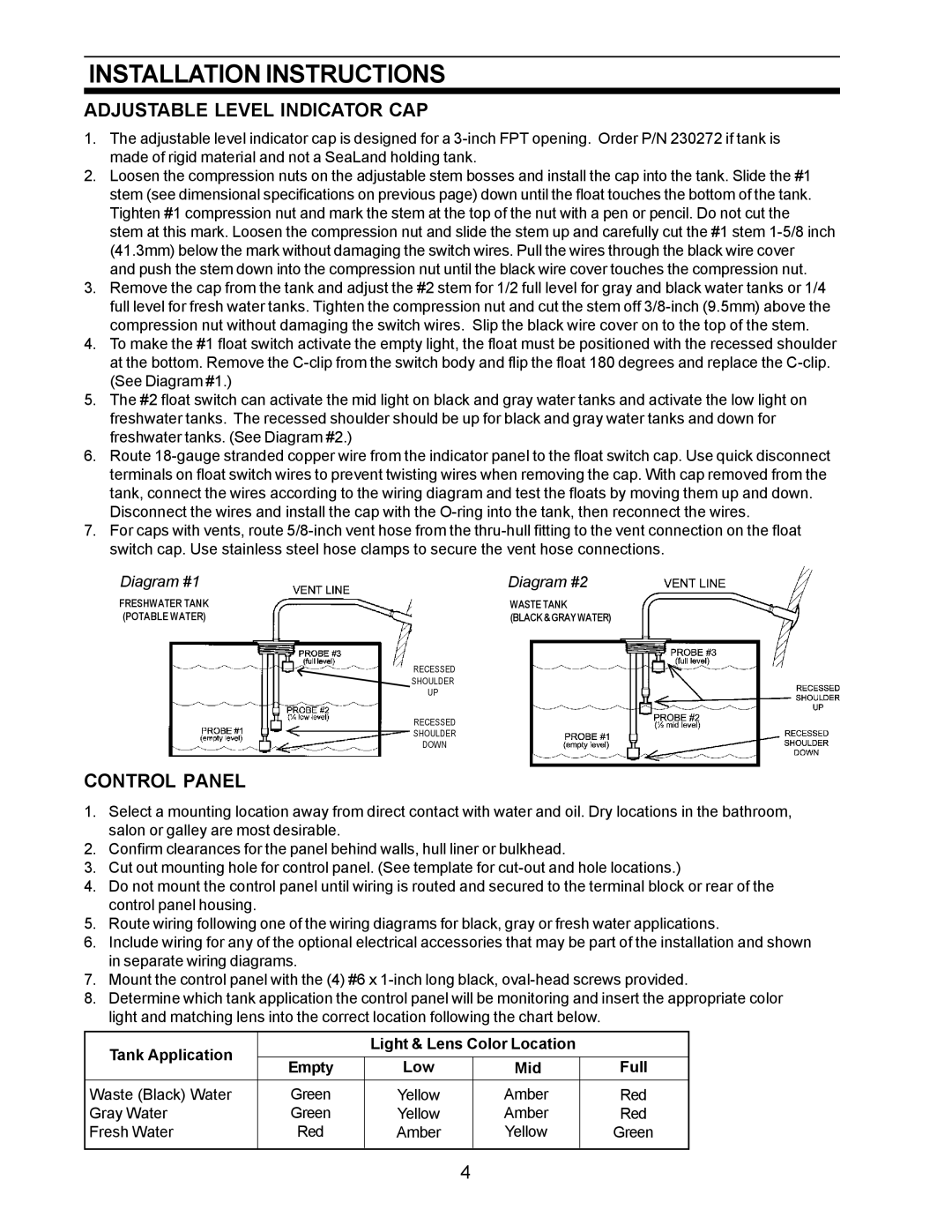
4.To make the #1 float switch activate the empty light, the float must be positioned with the recessed shoulder at the bottom. Remove the
5.The #2 float switch can activate the mid light on black and gray water tanks and activate the low light on freshwater tanks. The recessed shoulder should be up for black and gray water tanks and down for freshwater tanks. (See Diagram #2.)
6.Route
Disconnect the wires and install the cap with the
7.For caps with vents, route
Diagram #1 | Diagram #2 |
FRESHWATER TANK | WASTE TANK |
(POTABLE WATER) | (BLACK & GRAY WATER) |
RECESSED
SHOULDER
UP
RECESSED
SHOULDER
DOWN
CONTROL PANEL
1.Select a mounting location away from direct contact with water and oil. Dry locations in the bathroom, salon or galley are most desirable.
2.Confirm clearances for the panel behind walls, hull liner or bulkhead.
3.Cut out mounting hole for control panel. (See template for
4.Do not mount the control panel until wiring is routed and secured to the terminal block or rear of the control panel housing.
5.Route wiring following one of the wiring diagrams for black, gray or fresh water applications.
6.Include wiring for any of the optional electrical accessories that may be part of the installation and shown in separate wiring diagrams.
7.Mount the control panel with the (4) #6 x
8.Determine which tank application the control panel will be monitoring and insert the appropriate color light and matching lens into the correct location following the chart below.
Tank Application |
| Light & Lens Color Location |
| ||
|
|
|
| ||
Empty | Low | Mid | Full | ||
| |||||
Waste (Black) Water | Green | Yellow | Amber | Red | |
Gray Water | Green | Yellow | Amber | Red | |
Fresh Water | Red | Amber | Yellow | Green | |
|
|
|
|
| |
4