i i | illll, | ii,i ii ,ll | .... | , |
i/ J iui
MBLY
TO INSTALL THE UPPER HANDLE AND CRANK ASSEMBLY
•Remove the screws,flatwashers,to.washers and hexnuts secudngthe shifterplate inthe lowerholes of the lower handle..
•Loosen,t_Jtdo not remove,thescrews,flatwashers,
lockwashers, and hex nuts in the upperholesof the lowerhandle_
•Raise upper handle into operatingposition.Upper, handleshouldbe to the outsideof the lower handle and shifterplate to the inside.
•Replacethe screws0flatwashers,lockwashers, and hex nutsthroughthehandlesandshifterplate.Do not
lightenuntil all bolts are in ptace_T'_jhtenlefthand side first.
NOTE: Unless you have the assistanceof anotherper- son,itmay be easierto install one sideofthehandleat the time.
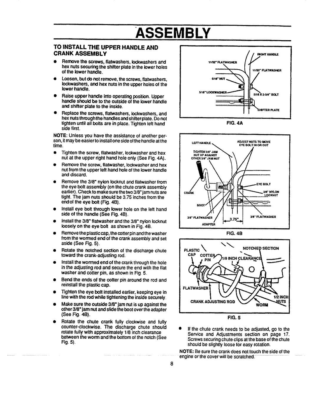
•Tightenthe screw, flat'washer,Iockwasherand hex nut at the upper dght hand hole only (See Fig,4A),
•Remove the screw,flatwasher,Iockwasherand hex
nutfrom the upper lefthand holeofthe lowerhandle and discard,
•Remove the 3/8" nylon iocknutand flatwasherfrom theeye bolt assembly(on lhe chutecrank assembly eadier)_Check tomake surethetwo3/8"jamnutsare tight.The jam nuts shouldbe 3.75 inches fromthe endof the eye bolt (Fig. 4B).
•Install eye bolt through lower hole on the left hand side of the handle (See Fig.,4B)_
•Installthe 3/8" ftatwasherand the3/8" nylonlocknut looselyon the eye bolt as shownin Fig_4Bo
•Removetheptasticcap, thecotterpinandthewasher from the wormedend ofthe crank assemblyand set aside (See Fig°5)_
•Rotate the notched sectionof the dischargechute towardthe crank*adjustingrod..
•Installthe wormed end of thecrankthroughthe hole in the adjustingrod and securethe end with the flat washer and cotter pin, as shownin Fig. 5
•Bendthe ends of the cotter pin aroundthe rodand reinstallthe plasticcap.
•Tighten the eye bolt installedearlier, keepingeye in linewiththe rodwhiletighteningthe insidesecurely
•Make sure the outside3/8" jam nut is upagainstthe other3/8" jam nutand slidethebootoverthe adapter (See F_,.4B).
•Rotate the chute crank fully clockwiseand fully
Fig. 5).
.................................................
_'tB"
FIG. 4A
=_
FIG. 5
•If the chute crank needs to be adjusted, go to the Service and Adjustments section on page 17_
Screwssecuringchuteclipsat thebase ofthechute shouldbe slightlyloose for easy rotation.
NOTE: Besurethe crankdoes nottouchthe sideofthe
engineor the coverwillbe scratched,:..................................................
8